
Heterogeneous end cover assembling equipment

A technology for assembling equipment and end caps, which is applied in the field of heterosexual end cap assembly equipment, and can solve problems such as time-consuming and laborious, uneven surface temperature of end caps, and generation of air bubbles

Inactive Publication Date: 2020-07-10
美弗莱克斯控制系统(嘉兴)有限公司
View PDF0 Cites 2 Cited by
  • Summary
  • Abstract
  • Description
  • Claims
  • Application Information

AI Technical Summary

Problems solved by technology

[0002] The flexible shaft is a shaft with little rigidity, elasticity and free bending transmission. It is used to connect two shafts with different axes and not in the same direction or with relative motion to transmit rotational motion and torque. It can flexibly transmit rotational motion and torque to In any position, the flexible shaft is named after its use. In mechanical design, it is used as a non-linear transmission or a transmission component between non-same planes. It can simplify the transmission machinery, and at the same time has high transmission accuracy and a wide range of applications, such as Concrete vibrators, wind picks, marine water pumps, transmissions of medical appliances and machine tools, and automobile odometers can all be driven by flexible shafts. In addition, flexible shafts can also ease the impact. In the production process of flexible shafts, one end of the flexible shaft It is necessary to assemble a heterosexual end cap and then cooperate with other equipment for connection. In the assembly process of the heterosexual end cap, the end cap and the flexible shaft are usually docked manually, and then the surface of the end cap is carried out by special equipment. Thermal processing, until the end cap shrinks to connect the end cap and the assembly of the flexible shaft, using manual operation is time-consuming and laborious, and it is easy to cause uneven surface temperature of the end cap during heating, and then generate air bubbles. Therefore, we propose a heterogeneous End cap assembly equipment to facilitate solving the problems raised above

Method used


Image

  • Heterogeneous end cover assembling equipment
  • Heterogeneous end cover assembling equipment
  • Heterogeneous end cover assembling equipment

Examples


Embodiment Construction

[0029] In order to make the object, technical solution and advantages of the present invention clearer, the present invention will be further described in detail below in conjunction with the accompanying drawings and embodiments. It should be understood that the specific embodiments described here are only used to explain the present invention, not to limit the present invention.

[0030] In the description of the present invention, it should be noted that the terms "center", "upper", "lower", "left", "right", "front", "rear", "vertical", "horizontal", The orientation or positional relationship indicated by "inner", "outer", etc. is based on the orientation or positional relationship shown in the drawings, and is only for the convenience of describing the present invention and simplifying the description, rather than indicating or implying that the referred device or element must have Certain orientations, constructed and operative in certain orientations, therefore are not t...


PUM


Abstract

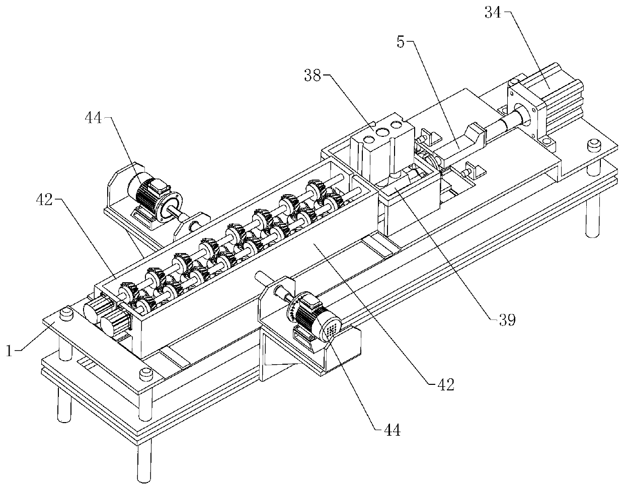
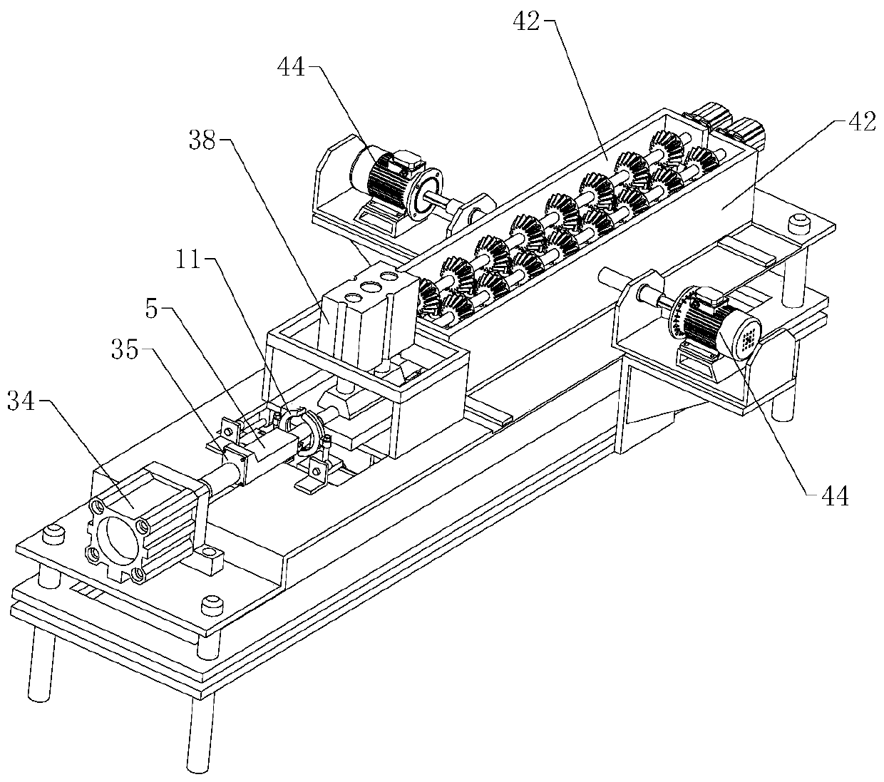
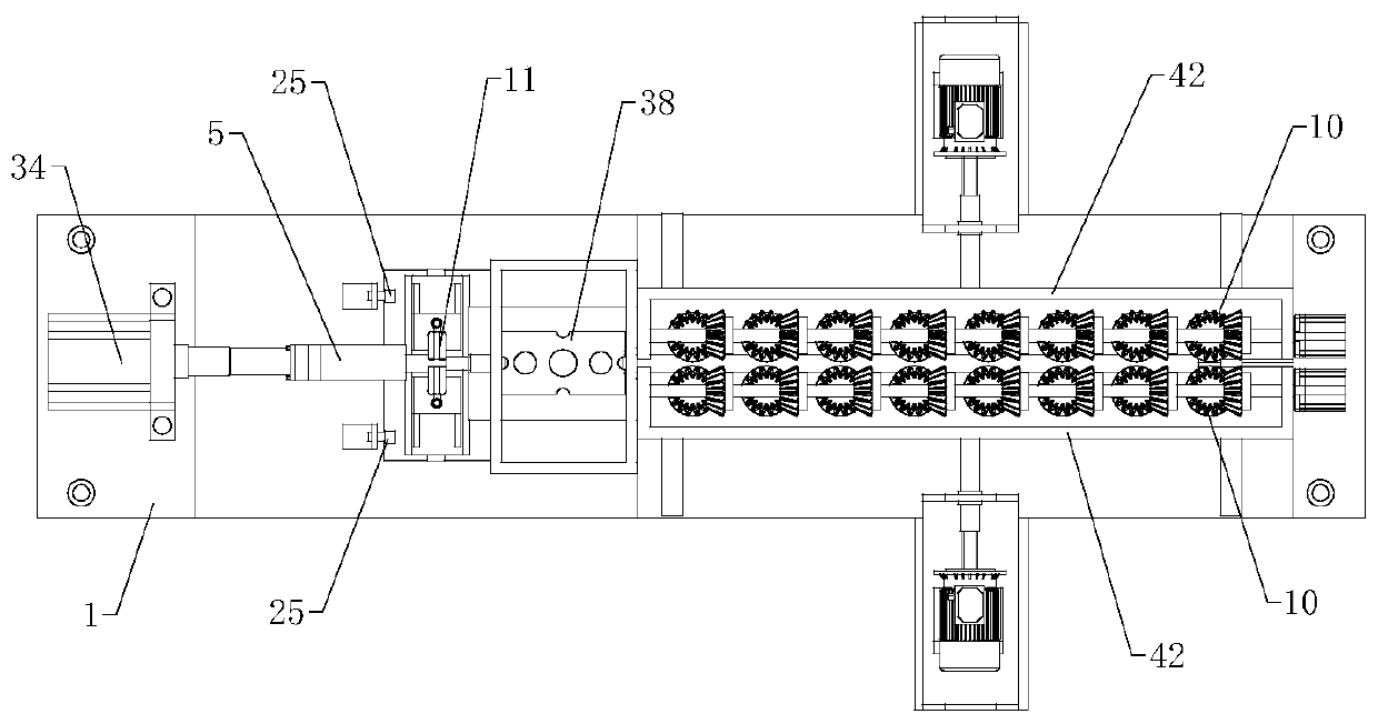
The invention relates to the technical field of heterogeneous end cover assembling, in particular to heterogeneous end cover assembling equipment. The equipment comprises a processing table and further comprises an end cover pushing mechanism, a flexible shaft locating pushing mechanism, a horizontal movement mechanism and a bidirectional heating mechanism, wherein the end cover pushing mechanismcomprises a butt-joint jig, a clamping groove is formed in the end, adjacent to the flexible shaft locating pushing mechanism, of the butt-joint jig, an end cover body is detachably arranged inside the clamping groove, the flexible shaft locating pushing mechanism comprises a flexible shaft sliding rail and two guide components, a locating groove used for containing a workpiece is formed in the flexible shaft sliding rail, a plurality of guide wheels are arranged on each guide component, the bidirectional heating mechanism comprises two arc-shaped heating pipes, a rectangular through opening used for avoiding movement of each arc-shaped heating pipe is formed in the processing table, and the bidirectional heating mechanism comprises a pushing plate which can move horizontally in the lengthdirection of the end cover body. Through the equipment, a heterogeneous end cover can be assembled automatically, the uniformity of the surface of the hot-worked heterogeneous end cover is improved,and processing quality is improved.

Description

technical field [0001] The invention relates to the technical field of heterosexual end cap assembly, in particular to a heterosexual end cap assembly equipment. Background technique [0002] The flexible shaft is a shaft with little rigidity, elasticity and free bending transmission. It is used to connect two shafts with different axes and not in the same direction or with relative motion to transmit rotational motion and torque. It can flexibly transmit rotational motion and torque to In any position, the flexible shaft is named after its use. In mechanical design, it is used as a non-linear transmission or a transmission component between non-same planes. It can simplify the transmission machinery, and at the same time has high transmission accuracy and a wide range of applications, such as Concrete vibrators, wind picks, marine water pumps, transmissions of medical appliances and machine tools, and automobile odometers can all be driven by flexible shafts. In addition, f...

Claims


Application Information

Patent Timeline
IPC IPC(8): B23P11/02
CPCB23P11/027
Inventor 杨明池徐春雷王立刚罗仟
Owner 美弗莱克斯控制系统(嘉兴)有限公司
Learn More