Assembly device for segmental prefabricated assembled bridge joint structure

A technology of prefabricated assembly and joint structure, which can be used in bridge construction, erection/assembly of bridges, bridges, etc., and can solve problems such as time-consuming and labor-intensive

Active Publication Date: 2020-08-07
江苏永捷特种装备有限公司
View PDF5 Cites 2 Cited by
  • Summary
  • Abstract
  • Description
  • Claims
  • Application Information

AI Technical Summary

Problems solved by technology

The double-layer bellows includes an outer tube, an inner tube sleeved inside the outer tube, and a strut between the inner and outer tubes. The outer tube and the inner tube are coaxial and have the same axial length. The ends of the outer tube and the inner tube both extend to the joint. At the joints of prefabricated assembled bridges, the outer tube of the double-layer bellows is trumpet-shaped, the inner tube is cylindrical, and the side wall has openings, which can be carried out without modifying the existing prestressed anchorage and grouting equipment. The sealing treatment of the joint section of the segmental beam has simple connection operation and reliable construction quality, which not only facilitates the beam-through operation of the prestressed steel strand, but also enhances the airtightness of the pipeline and increases the thickness of the protective layer of the prestressed steel strand. Thereby greatly improving the durability of segmental prefabricated assembled bridges, reducing potential safety hazards, and facilitating later maintenance and repairs. When assembling segmental prefabricated assembled bridges, the segmental trial assembly is generally performed by manual machine updating and assembly, which is time-consuming and laborious. Therefore, , we propose an assembly equipment for segmental prefabricated assembled bridge joint structures in order to solve the problems raised above

Method used


Image

  • Assembly device for segmental prefabricated assembled bridge joint structure
  • Assembly device for segmental prefabricated assembled bridge joint structure
  • Assembly device for segmental prefabricated assembled bridge joint structure

Examples


Embodiment Construction

[0026] In order to make the object, technical solution and advantages of the present invention clearer, the present invention will be further described in detail below in conjunction with the accompanying drawings and embodiments. It should be understood that the specific embodiments described here are only used to explain the present invention, not to limit the present invention.

[0027] In the description of the present invention, it should be noted that the terms "center", "upper", "lower", "left", "right", "front", "rear", "vertical", "horizontal", The orientation or positional relationship indicated by "inner", "outer", etc. is based on the orientation or positional relationship shown in the drawings, and is only for the convenience of describing the present invention and simplifying the description, rather than indicating or implying that the referred device or element must have Certain orientations, constructed and operative in certain orientations, therefore are not t...


PUM


Abstract

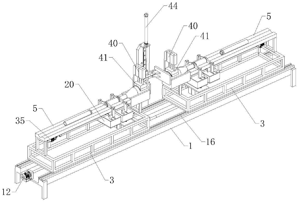
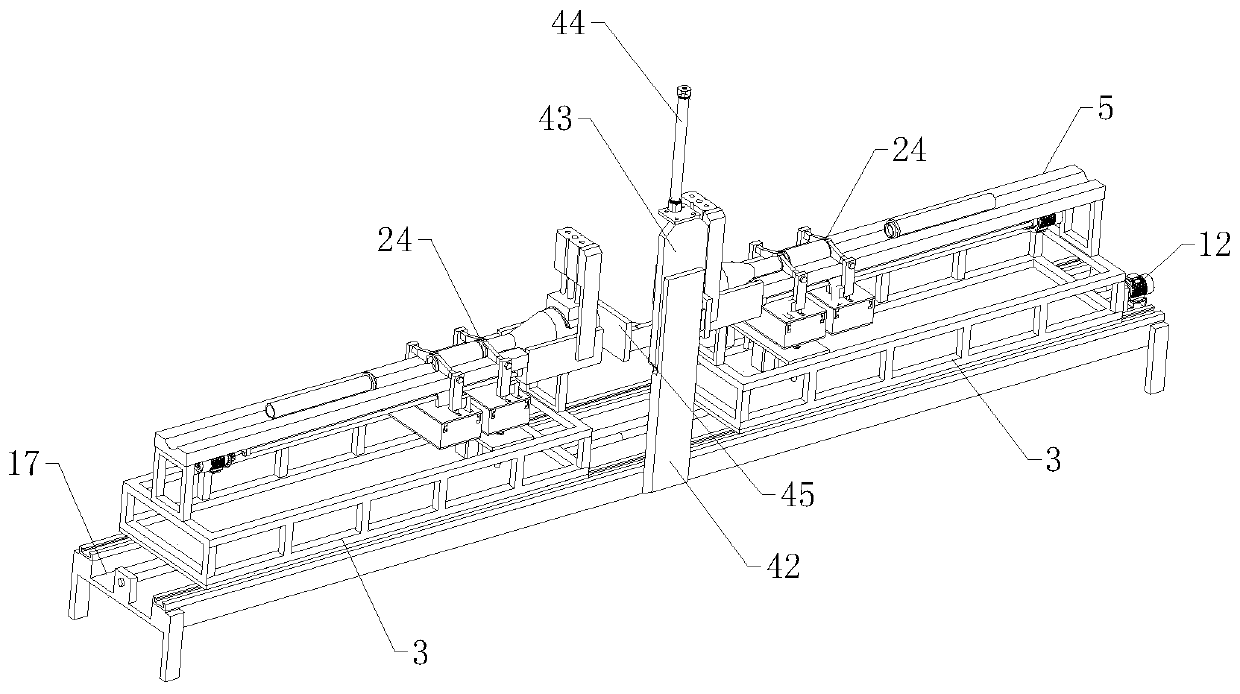
The invention relates to the technical field of segmental prefabricated assembled bridges, in particular to an assembly device of a segmental prefabricated assembled bridge joint structure. The devicecomprises a machining table, an opposite moving mechanism is arranged at the top of the machining table; the opposite moving mechanism comprises two moving frames which are horizontally and symmetrically arranged; a lifting abutting mechanism is arranged between the two moving machines. A horizontally arranged placing table is arranged above each moving frame; a sliding groove is formed in the top of each containing table. Positioning grooves are respectively formed in the adjacent ends of two placing tables; a lifting mechanism is arranged below one end, close to the positioning groove, of each placing table; a first positioning mechanism capable of abutting against a workpiece is arranged above each lifting mechanism. A horizontal moving mechanism is further arranged below each placingtable, the working end of each horizontal moving mechanism is provided with a second positioning mechanism capable of abutting against a corresponding workpiece, the equipment can automatically assemble the segmental prefabricated assembled bridge joint, labor force is reduced, and efficiency is improved.

Description

technical field [0001] The invention relates to the technical field of segmental prefabricated assembled bridges, in particular to an assembly device for segmental prefabricated assembled bridge joint structures. Background technique [0002] my country's patent application number: CN201910832237.9; public date: 2019.11.19 discloses a segmental prefabricated assembled bridge joint structure and its construction method. Bellows, inner pipe joints, epoxy resin glue between joints and sealing gaskets, etc.; the double-layer plastic bellows is a structure that gradually changes from a single-layer pipe to a double-layer pipe. The side of the seam is a single-layer corrugated pipe, and the side close to the joint of the segmental prefabricated and assembled bridge is a trumpet-shaped double-layer corrugated pipe. The inner and outer pipe walls of the single-layer corrugated pipe and double-layer corrugated pipe are corrugated . The double-layer bellows includes an outer tube, an i...

Claims


Application Information

Patent Timeline
Patent Type & Authority Applications(China)
IPC IPC(8): E01D21/00
CPCE01D21/00
Inventor 王文洋
Owner 江苏永捷特种装备有限公司
Why Eureka
Try Eureka