A clamping tool for automatic processing of flat parts

A technology for clamping tooling and parts, applied in the field of automated processing, can solve problems such as inability to automatically turn over, and achieve the effect of protecting from deformation and improving processing efficiency

Active Publication Date: 2021-04-23
SUZHOU ODIHUA ELECTRONIC CO LTD
View PDF15 Cites 1 Cited by
  • Summary
  • Abstract
  • Description
  • Claims
  • Application Information

AI Technical Summary

Problems solved by technology

[0004] The technical problem to be solved by the present invention is to provide a clamping tool for the automatic processing of flat parts, including a base, which is equipped with a moving seat capable of moving on the base through a moving seat drive unit. There is an overturning support seat, on which a clamping plate for clamping the workpiece is hinged, and the clamping plate is connected with an overturning unit for driving the clamping plate to turn over, and the two ends of the moving seat are also equipped with a clamping plate for supporting and pressing clamping. The pressing unit of the plate, the moving seat is also provided with a support unit for preventing the deformation of the workpiece during processing. The supporting unit is detachably installed on the moving seat to solve the problem of processing flat parts in the prior art. The problem of not being able to automatically flip when

Method used


Image

  • A clamping tool for automatic processing of flat parts
  • A clamping tool for automatic processing of flat parts
  • A clamping tool for automatic processing of flat parts

Examples


Embodiment 1

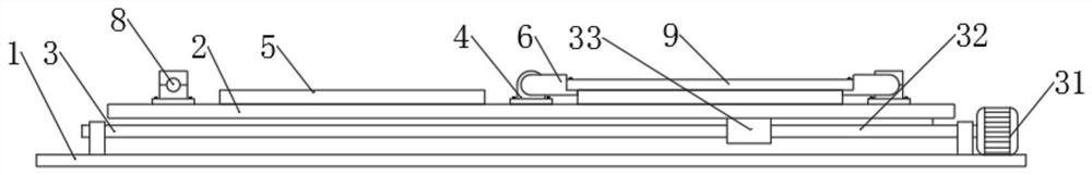
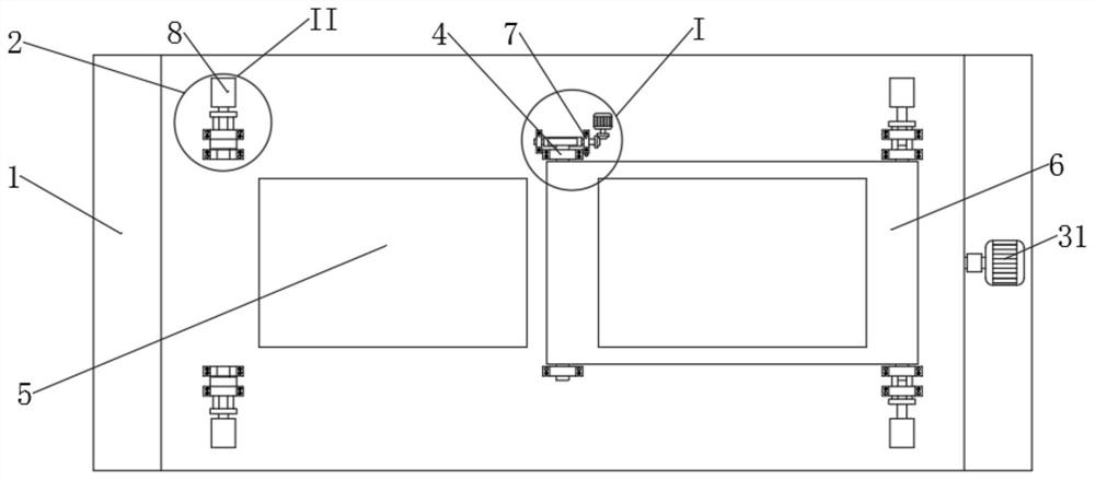
[0024] Depend on Figure 1 ~ Figure 4 As shown, a clamping tool for automatic processing of flat parts, including a base 1, the base 1 is equipped with a moving base 2 capable of moving on the base 1 through the driving unit 3 of the moving base, and the moving base 2 is provided with an overturning support seat 4. A clamping plate 6 for clamping the workpiece 9 is hinged on the turning support base 4, and the clamping plate 6 is connected with a turning unit 7 for driving the clamping plate 6 to turn over. Press the pressing unit 8 of the clamping plate 6, and the moving base 2 is also provided with a support unit 5 for preventing the deformation of the workpiece 9 during processing, and the supporting unit 5 is detachably installed on the moving base 2 superior;

[0025] The base 1 is a flat plate, and the base 1 is provided with a mounting hole for being installed on a plate processing device;

[0026] The mobile seat 2 is a flat plate, and the mobile seat drive unit 3 in...

Embodiment 2

[0035] Depend on Figure 1 ~ Figure 4As shown, a clamping tool for automatic processing of flat parts, including a base 1, the base 1 is equipped with a moving base 2 capable of moving on the base 1 through the driving unit 3 of the moving base, and the moving base 2 is provided with an overturning support seat 4. A clamping plate 6 for clamping the workpiece 9 is hinged on the turning support base 4, and the clamping plate 6 is connected with a turning unit 7 for driving the clamping plate 6 to turn over. Press the pressing unit 8 of the clamping plate 6, and the moving base 2 is also provided with a support unit 5 for preventing the deformation of the workpiece 9 during processing, and the supporting unit 5 is detachably installed on the moving base 2 superior;

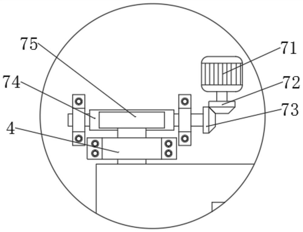
[0036] Preferably, in this embodiment, the first motor 71 and the worm 74 are connected through the first bevel gear 72 and the second bevel gear 73, the first bevel gear 72 is fixed on the output shaft of the firs...


PUM


Abstract

The invention discloses a clamping tool for automatic processing of flat parts, relates to the field of automatic processing, and solves the problem in the prior art that the flat parts cannot be turned over automatically when processing flat parts. The drive unit of the mobile seat is equipped with a mobile seat that can move on the base. The mobile seat is provided with an overturning support seat. A clamping plate for clamping the workpiece is hinged on the overturning support seat. Turning unit, the two ends of the moving seat are also equipped with a pressing unit for supporting and pressing the clamping plate, and the moving seat is also equipped with a supporting unit for preventing the deformation of the workpiece during processing. The supporting unit is detachable The method is installed on the moving seat; the invention can improve the processing efficiency of flat workpieces, and at the same time, can protect flat workpieces from deformation during processing.

Description

technical field [0001] The invention relates to the field of automatic processing, in particular to a clamping tool for automatic processing of flat parts. Background technique [0002] When clamping the tooling, the tool that clamps the part during the part processing ensures that the part does not shift or deform during the processing. [0003] Chinese Patent Publication No. "CN109079042A" discloses a plate clamping tool, which relates to the field of fixture technology, and includes a base on which a slide rail is fixedly connected. The slide rail is provided with a drive structure and is movably connected at both ends. C”-shaped skateboard, the bottom of the skateboard is equipped with a rack. The tooling has a simple structure and is easy to operate. By setting the driving structure, the position change of the skateboard on the slide rail can be realized. A. The special-shaped clamping block B and the spring realize the splint clamping of plates with different widths a...

Claims


Application Information

Patent Timeline
Patent Type & Authority Patents(China)
IPC IPC(8): B23Q3/08B23Q7/02
CPCB23Q3/08B23Q7/02
Inventor 史骅婷
Owner SUZHOU ODIHUA ELECTRONIC CO LTD
Why Eureka
Try Eureka