
Fully mechanized mining face end conveying and supporting integrated supporting device

A fully mechanized mining face and support device technology, applied to mining equipment, earthwork drilling, mine roof supports, etc., can solve problems such as difficulty in controlling the top plate at the end, squeezing the passage space, and the impact of continuous advancement. Anchoring and auxiliary push, slow down the chance of sliding, improve the effect of control effect

Active Publication Date: 2020-07-10
TIANDI SCI & TECH CO LTD +1
View PDF8 Cites 4 Cited by
  • Summary
  • Abstract
  • Description
  • Claims
  • Application Information

AI Technical Summary

Problems solved by technology

[0003] 1) Since the top of the long top beam end bracket is far away from the support point of the column, the effective support force is very small, and it is often in the state of being stuck, which cannot effectively play a supporting role, resulting in deformation of the end and squeezing the limited passage space , especially for the broken roof, it is very difficult to control the end roof
[0004] 2) The head and tail of the existing scraper conveyor are both in an unconstrained state, and there is no special tilt adjustment mechanism. The forward movement is achieved by the hydraulic support. , the conveyor and support interfere with the coal wall, requiring manual adjustment, which has a great impact on continuous advancement
[0005] The patented special-shaped support equipment for the end of the fully mechanized mining face (201810444060.0) provides an end support equipment that can support and seal the entire section of the empty roof area at the tail of the conveyor. However, the support equipment and the conveyor The space is relatively independent, which does not solve the problem of the original end bracket super long control top distance

Method used


Image

  • Fully mechanized mining face end conveying and supporting integrated supporting device
  • Fully mechanized mining face end conveying and supporting integrated supporting device
  • Fully mechanized mining face end conveying and supporting integrated supporting device

Examples


Embodiment Construction

[0019] The present invention will be further described below in conjunction with the accompanying drawings.

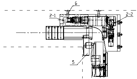
[0020] figure 1 It is the layout diagram of the support at the end of the transport trough in the existing fully mechanized mining face. It is composed of the hydraulic support 1' at the end of the long top beam and the hydraulic support 3 in advance. The transmission part of the unconstrained scraper conveyor 2' consists of The space protection formed by the top beam of the end hydraulic support 1', in order to realize full section support, the length of the top beam is L.

[0021] Such as Figure 2~4 As shown, the integrated support device 4 of the present invention is placed between the terminal hydraulic support 1 and the forward hydraulic support 3 along the groove. The terminal hydraulic support 1 adopts a telescopic roof beam structure, and the terminal hydraulic support 1 1', the length of the top beam is significantly shortened.

[0022] The integrated supp...


PUM


Abstract

The invention discloses fully mechanized mining face end supporting equipment and specifically relates to a conveying and supporting integrated end supporting device collaboratively designed with a scraper conveyor. The integrated supporting device is composed of a top beam, a base, stand columns, a middle supporting frame and a stabilizing mechanism. The base is connected with the end of the scraper conveyor into a whole. The force bearing points of the stand columns are locally reinforced at the base. The middle supporting frame is arranged between the top beam and the base and serves as a cover plate of a driving part, and space utilization of intensive devices is realized. According to the conveying and supporting integrated supporting device arranged at the end, the constraint and adjustment functions are added to the head or the tail of the scraper conveyor, and the tendency of upward moving and downward sliding is slowed down; a three-level collaborative supporting mode of an end hydraulic support, an end conveying and supporting integrated supporting device and a fore support is formed at the end of a fully mechanized mining face. The problem of ineffective supporting of asuperlong top beam of a traditional end hydraulic support is solved. The mining face end surrounding rock control capability is improved. The fully mechanized mining face end supporting equipment provides a device support for high-yield and high-efficiency mining of complicated coal seams.

Description

technical field [0001] The invention relates to end support equipment for a fully mechanized coal mining face in underground mining, in particular to a "transportation-support" integrated support device in which an end hydraulic support and a scraper conveyor cooperate. Background technique [0002] Longwall comprehensive mechanized mining (mechanized mining) is the current mainstream coal mining method in underground coal mines. The fully mechanized mining face equipment is composed of hydraulic supports, scraper conveyors and shearers. The scraper conveyor is used as the core of the shearer The pulling point of the walking part and the hydraulic support is in an unconstrained state in the inclined direction of the working face, and a certain gap is kept with the coal wall of the transportation lane and the return air lane to facilitate advancement. Placed at the nose and tail of the machine, the motor, coupling and reducer take up a lot of space, so it is equipped with a h...

Claims


Application Information

Patent Timeline
IPC IPC(8): E21D23/00E21D23/04E21D23/06
CPCE21D23/0047E21D23/0472E21D23/0418E21D23/0445E21D23/063
Inventor 张德生徐亚军王彪谋任怀伟程骏李提建张金虎
Owner TIANDI SCI & TECH CO LTD
Learn More