
Impeller with adjustable angle

An adjustable impeller technology, which is applied to components of pumping devices for elastic fluids, non-variable pumps, machines/engines, etc., can solve problems such as the inability of the blades to rotate and the impeller to be hot

Pending Publication Date: 2020-07-10
嵊州市远翔电器有限公司
View PDF0 Cites 0 Cited by
  • Summary
  • Abstract
  • Description
  • Claims
  • Application Information

AI Technical Summary

Problems solved by technology

[0004] The purpose of the present invention is to provide an angle-adjustable impeller, which solves the problem that the blades in the impeller cannot rotate. At the same time, if the impeller is rubbed against the air for a long time, the impeller will be subjected to the friction force of the air, which will cause the impeller to become hot. problem solving

Method used


Image

  • Impeller with adjustable angle
  • Impeller with adjustable angle
  • Impeller with adjustable angle

Examples


Embodiment Construction

[0022] The following descriptions are only preferred implementations of the present invention, and the scope of protection is not limited to this embodiment. All technical solutions under the idea of ​​the present invention shall belong to the scope of protection of the present invention. At the same time, it should be pointed out that for those skilled in the art, some improvements and modifications without departing from the principle of the present invention should also be regarded as the protection scope of the present invention.

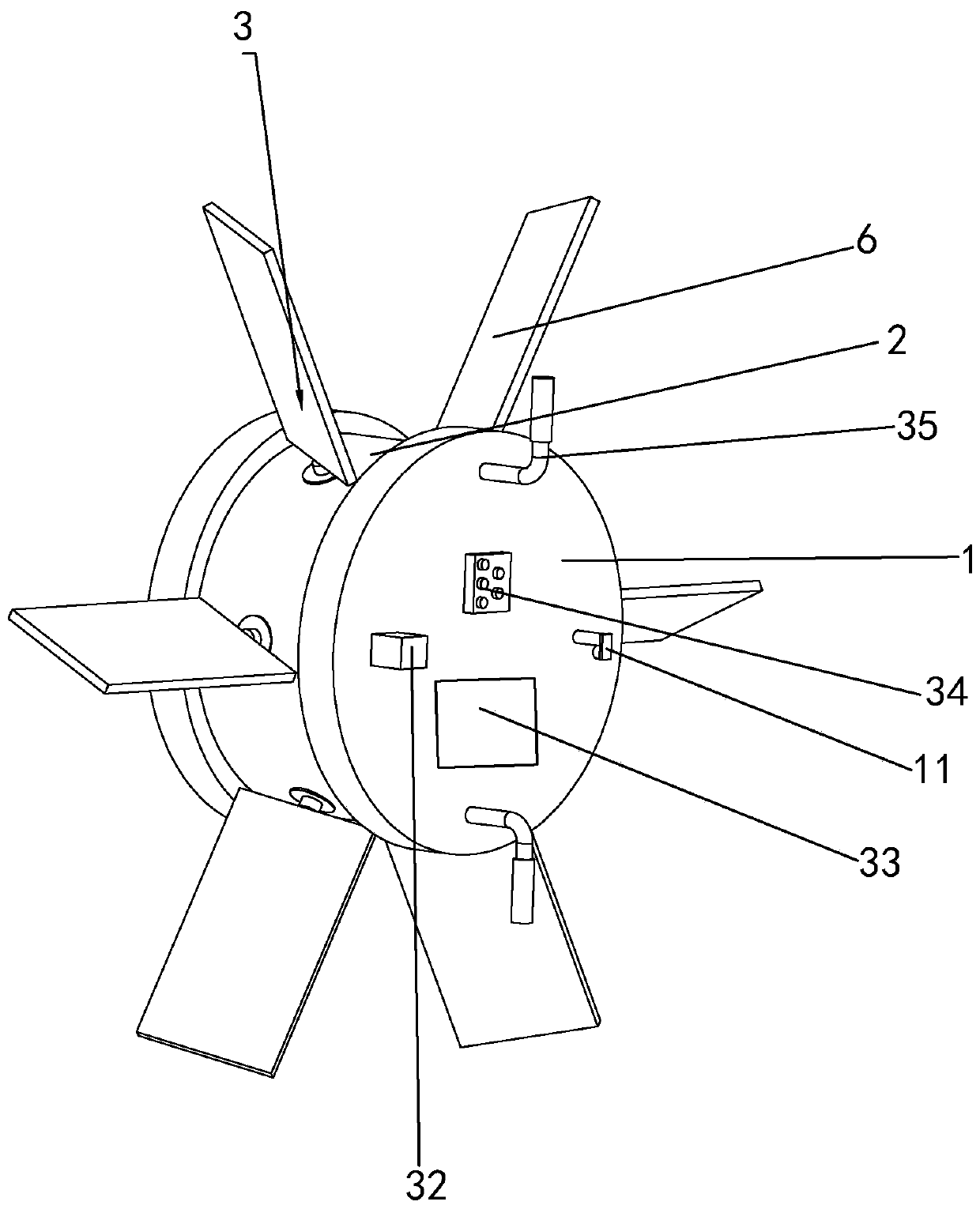
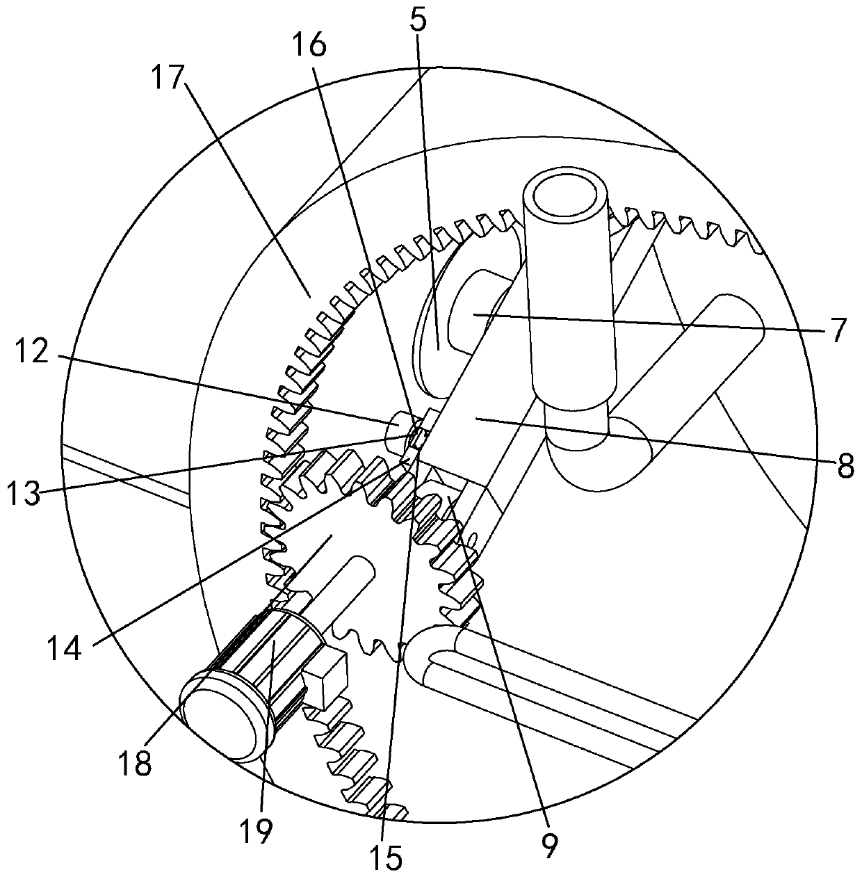
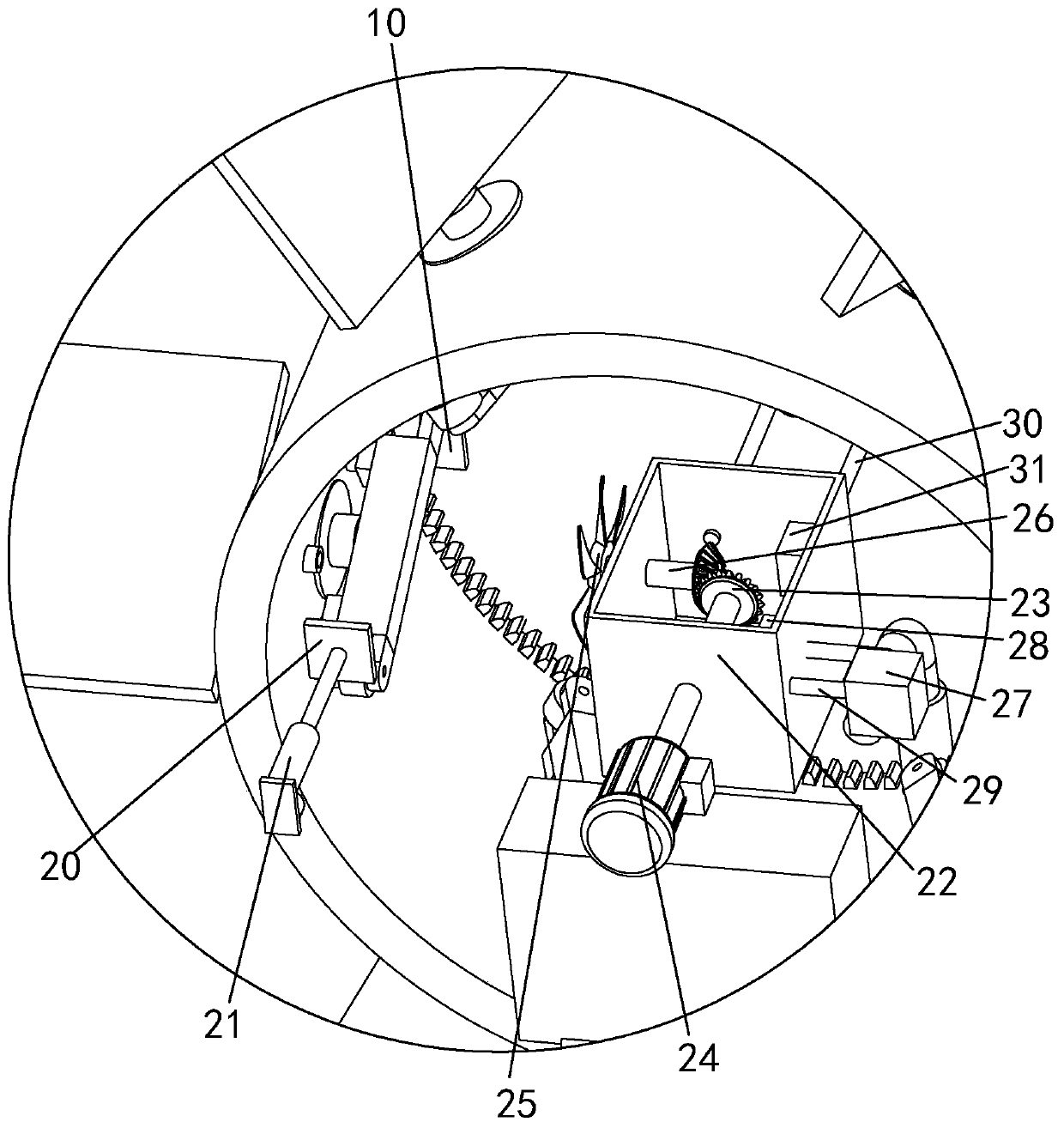
[0023] Such as Figures 1 to 3 , an angle-adjustable impeller, including an impeller body 1 and a rotating disk-2 rotatably arranged in the impeller body 1, including an adjusting device 3 rotatably arranged on the side wall of the rotating disk-2 for driving airflow and fixed on the impeller The cooling circulation device 4 on the side wall of the body 1 is used to cool the impeller body 1. When the personnel need to blow air, the adjustment de...


PUM


Abstract

The invention discloses an impeller with an adjustable angle. The impeller with the adjustable angle comprises an impeller body and a first rotating disc rotatably arranged in the impeller body; the impeller with the adjustable angle comprises an adjustment device which is rotatably arranged on one side wall of the rotating disc and is used for driving an air flow, and a cooling circulating devicewhich is fixed to the side wall of the impeller body and is used for cooling the impeller body. The problem that blades in the impeller cannot rotate is solved; and meanwhile, the problem of a phenomenon that the impeller can be hot because the impeller is in friction with air for a long time and the impeller can be subjected to friction force of the air is solved.

Description

technical field [0001] The invention relates to the technical field of fan equipment, in particular to an angle-adjustable impeller. Background technique [0002] The fan is a machine that relies on the input mechanical energy to increase the gas pressure and discharge the gas. It is a driven fluid machine. Fan is the customary abbreviation for gas compression and gas conveying machinery in China. Generally speaking, fans include ventilators, blowers, and wind generators. [0003] During the operation of the traditional impeller, the blades in the impeller cannot rotate. At the same time, when the impeller is in long-term operation, the impeller will rub against the air for a long time, and the impeller will be subjected to the friction force of the air, which will cause the impeller to become hot. Contents of the invention [0004] The purpose of the present invention is to provide an angle-adjustable impeller, which solves the problem that the blades in the impeller can...

Claims


Application Information

Patent Timeline
IPC IPC(8): F04D29/28F04D29/58
CPCF04D29/281F04D29/287F04D29/5813F04D29/584
Inventor 吕波
Owner 嵊州市远翔电器有限公司
Learn More