Device and method for positioning and measuring position of a piston ring groove in automatic piston assembly

A positioning measurement and automatic assembly technology, applied in the direction of measuring devices, optical devices, instruments, etc., can solve the problems of surface damage of parts, inability to realize multi-variety flexible automatic assembly production, and difficulties in flexible automatic assembly of piston assemblies, etc., to achieve high efficiency The effect of positioning

Pending Publication Date: 2020-07-10
BEIJING RES INST OF AUTOMATION FOR MACHINERY IND
View PDF0 Cites 0 Cited by
  • Summary
  • Abstract
  • Description
  • Claims
  • Application Information

AI Technical Summary

Problems solved by technology

In this link, on the one hand, the piston ring groove and the piston ring assembly and matching precision are required to be high; As a result, when the equipment for assembling piston rings is assembling the piston rings, the piston rings cannot be correctly aligned with the position of the piston ring groove on the piston, which brings difficulties to the flexible and automatic assembly of the piston assembly
Therefore, at present, the factory has been using semi-automatic assembly of single-variety special plane or manual assembly in its assembly process, which cannot realize multi-variety flexible automatic assembly production
The fundamental reason is that the position of the piston ring groove relative to the equipment cannot be accurately and conveniently located
In addition, the existing method of directly measuring the position of the piston ring groove with a measuring tool needs to contact the workpiece, which may cause surface damage of the part, which cannot meet the requirements

Method used


Image

  • Device and method for positioning and measuring position of a piston ring groove in automatic piston assembly
  • Device and method for positioning and measuring position of a piston ring groove in automatic piston assembly
  • Device and method for positioning and measuring position of a piston ring groove in automatic piston assembly

Examples


Embodiment Construction

[0062] The technical solution of the present invention will be described in detail below in conjunction with the accompanying drawings and specific embodiments to further understand the purpose, solution and effect of the present invention, but it is not intended to limit the scope of protection of the appended claims of the present invention.

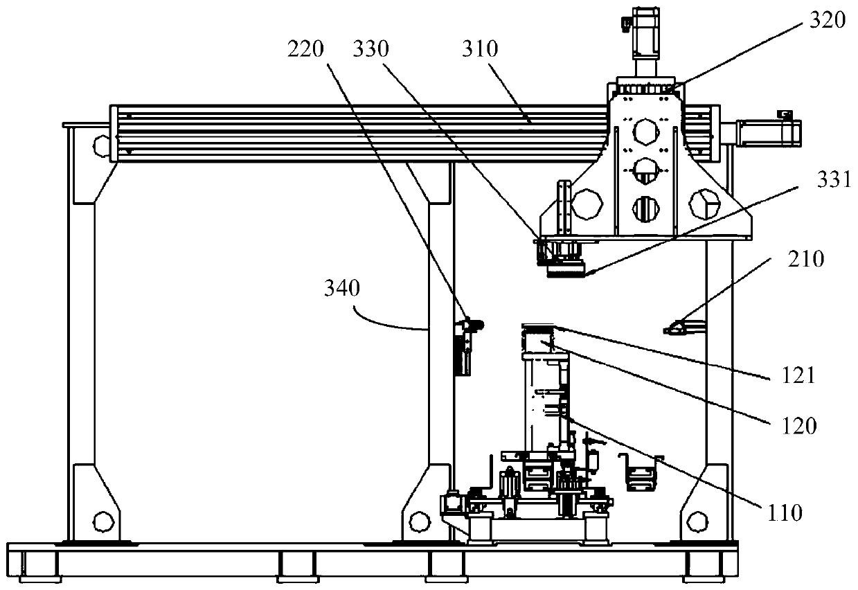
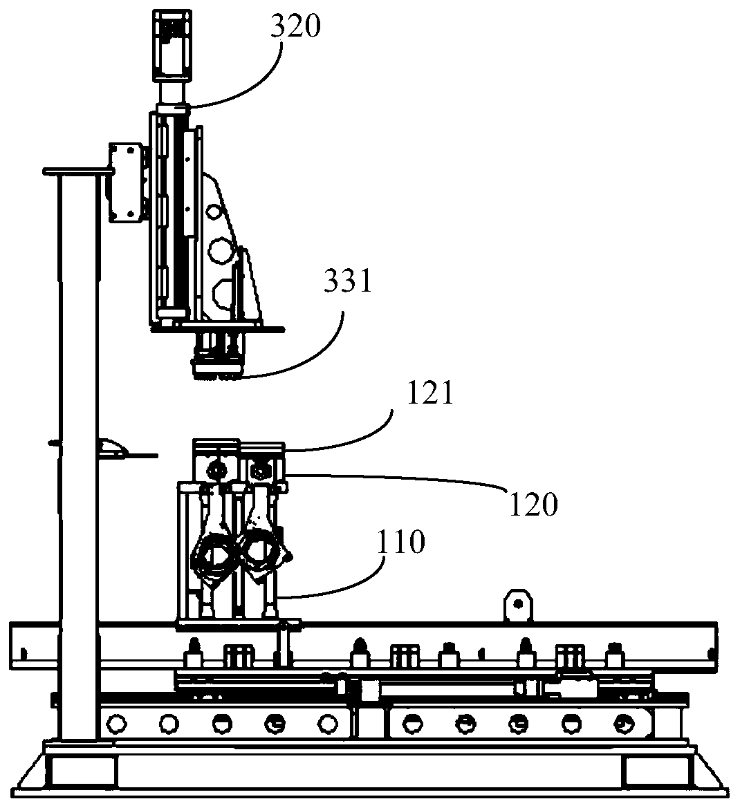
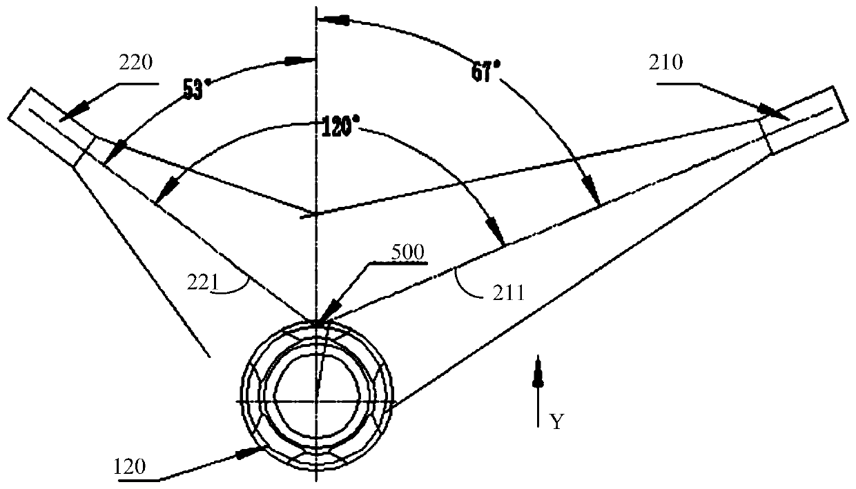
[0063] figure 1 and figure 2 Respectively, the front view and the side view of the positioning measuring device of the present invention, such as figure 1 and figure 2 as shown, Figure 4a , 4b , 4c are the front view, side view and top view of the tray of the positioning measurement device of the present invention, wherein, Figure 4a Also shows the relative position of the piston connecting rod, the invention provides a positioning measuring device for the position of the piston ring groove in the automatic assembly of the piston, including:

[0064] Tray 110;

[0065] A piston 120 with an annular groove 121 is arranged in th...


PUM


Abstract

The invention discloses a device and a method for positioning and measuring a position of a piston ring groove in automatic piston assembly. The device comprises a tray, a piston, a camera, a liftingservo sliding table, a pressing head and an image recognition and calculation unit, wherein the piston has a ring groove and is arranged in a groove of the tray; the camera is arranged on one side ofthe piston; the lifting servo sliding table is arranged above the tray; the pressure head is provided with a piston ring and is arranged on the lifting servo sliding table; and the image recognition and calculation unit is in signal connection with the camera and is in driving connection with the lifting servo sliding table. The device and the method adopt a visual system non-contact measurement mode, can position the position of the piston ring groove simply, conveniently, reliably and efficiently, and provide a reliable basis for flexible and automatic assembly of the piston ring.

Description

technical field [0001] The invention relates to the piston automatic assembly technology in the field of engines, in particular to a positioning and measuring device and method for the position of the piston ring groove in the automatic piston assembly. Background technique [0002] During the flexible automatic assembly process of the engine piston assembly, it is an essential link to assemble three piston rings on the piston. In this link, on the one hand, the piston ring groove and the piston ring assembly and matching precision are required to be high; As a result, when the piston ring is assembled by the equipment for assembling the piston ring, the piston ring cannot be correctly aligned with the position of the piston ring groove on the piston, which brings difficulties to the flexible automatic assembly of the piston assembly. Therefore, at present, the factory has been using single-variety special machine semi-automatic assembly or manual assembly in its assembly p...

Claims


Application Information

Patent Timeline
Patent Type & Authority Applications(China)
IPC IPC(8): G01B11/00
CPCG01B11/00G01B11/002
Inventor 程金周祺张希
Owner BEIJING RES INST OF AUTOMATION FOR MACHINERY IND
Why Eureka
Try Eureka