Disc type permanent magnet motor applied to crane

A technology for permanent magnet motors and cranes, applied in electromechanical devices, emergency power supply arrangements, magnetic circuits, etc., can solve the problems of reduced service life of motors, complex structure of cranes, and inaccurate positioning, so as to avoid the impact of frequent jogging and save energy. Electric energy and material cost, effect of extending service life

Pending Publication Date: 2020-07-10
HEBEI XINGLONG ELEVATORING EQUIP CO LTD
View PDF0 Cites 2 Cited by
  • Summary
  • Abstract
  • Description
  • Claims
  • Application Information

AI Technical Summary

Problems solved by technology

[0002] At present, most of the motors used for walking and lifting on cranes are driven by Y series asynchronous motor acceleration and deceleration machines. The volume of the equipment is very large, and the noise is large. Repeated jogging can achieve the goal, because repeated jogging makes the motor run in the starting state for a long time, resulting in large current, wasting electric energy, and reducing the service life of the motor; especially when the load is low and the speed is low, the efficiency of the asynchronous motor is very low, and the power factor is also low, so the system efficiency is very low
[0003] There are also some cranes that use frequency conversion technology, which can adjust the speed of the motor due to frequency conversion, which solves the above problems, but in the process of use, it is found that the low-speed performance is not good, and the cost is high, the frequency conversion motor is large in size, and the startup noise is large. question
[0004] To sum up, the current cranes have complex structures, low efficiency, large volume of the entire lifting mechanism, high noise, and difficulty in cooling the motor.

Method used


Image

  • Disc type permanent magnet motor applied to crane
  • Disc type permanent magnet motor applied to crane
  • Disc type permanent magnet motor applied to crane

Examples


Embodiment Construction

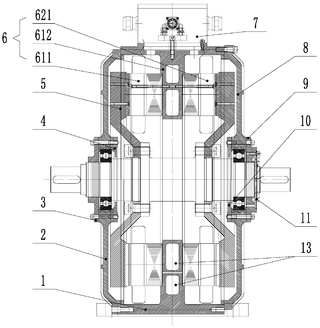
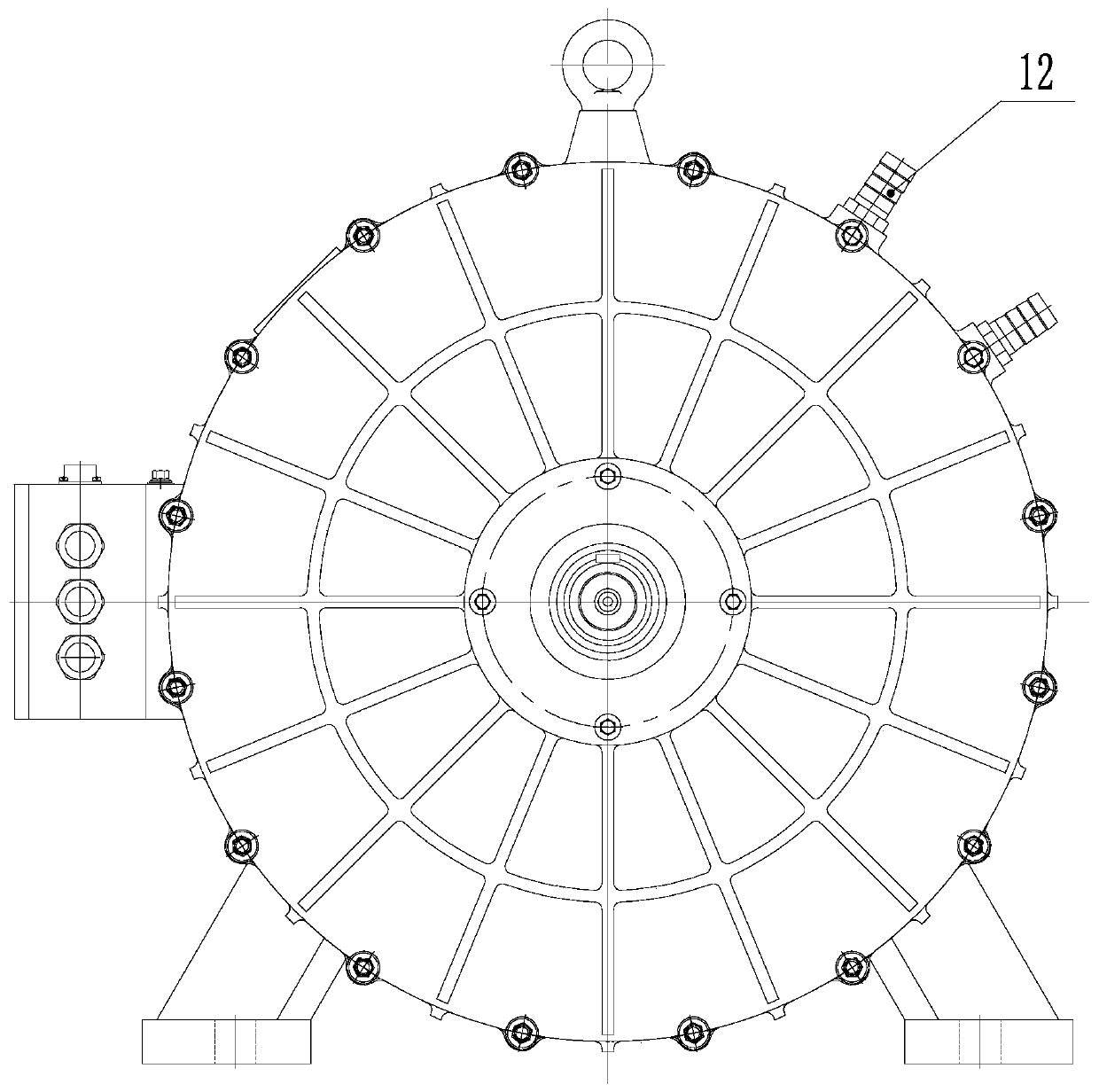
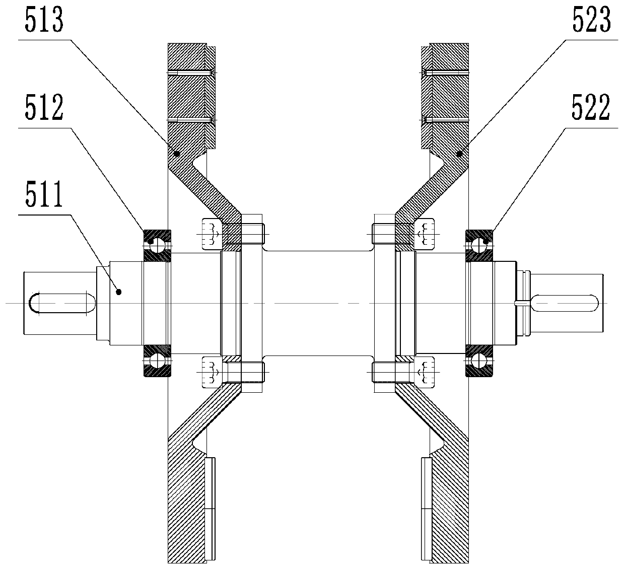
[0034] like Figure 1-Figure 7 As shown, a disc permanent magnet motor applied to a crane includes a casing set, a motor shaft 511, a rotor assembly 5 and a stator assembly 6, and the number of groups of the rotor assembly 5 is the same as the number of groups of the stator assembly 6 Equal and greater than or equal to 2. The casing set surrounds a hollow cavity, the motor shaft 511 passes through the casing set horizontally, and is rotatably connected with the casing set, and the motor shaft 511 is located on the casing The outside of the kit is provided with a double output shaft extension structure for transmission; the stator assembly 6 is located in the cavity of the casing kit and is fixedly connected with the casing kit, and the stator assembly 6 is connected to the motor shaft 511 There is a radial gap between the circumferences, and the rotor assembly 5 is fixed on the motor shaft 511, and the rotor in the rotor assembly 5 is matched with the stator in the stator ass...


PUM


Abstract

The invention relates to the field of permanent magnet synchronous motors, and discloses a disc type permanent magnet motor applied to a crane, which comprises a casing suite, a motor shaft, rotor assemblies and stator assemblies. The number of the rotor assemblies and the number of the stator assemblies are equal and are greater than or equal to 2. A hollow cavity is defined by the casing suite,and the motor shaft horizontally penetrates through the casing suite and is connected with the casing suite in a rotating mode. The stator assemblies are located in the cavity of the casing suite andare fixedly connected with the casing suite. A radial gap is formed between each stator assembly and the circumference of the motor shaft. The rotor assemblies are fixedly arranged on the motor shaft,and rotors in the rotor assemblies and stators in the stator assemblies are in one-to-one matching correspondence and are used for generating electromagnetic torque for driving the motor shaft. A horizontal double-output shaft extension structure is adopted, and the two shaft extension ends of the motor can be respectively provided with a planetary gear reduction box and a brake, so that the sizeof the motor is reduced.

Description

technical field [0001] The invention relates to the field of permanent magnet synchronous motors, in particular to a disc permanent magnet motor applied to cranes. Background technique [0002] At present, most of the motors used for walking and lifting on cranes are driven by Y series asynchronous motor acceleration and deceleration machines. The volume of the equipment is very large, and the noise is large. Repeated jogging can achieve the goal, because repeated jogging makes the motor run in the starting state for a long time, resulting in large current, wasting electric energy, and reducing the service life of the motor; especially when the load is low and the speed is low, the efficiency of the asynchronous motor is very low, and the power factor is also low, so the system efficiency is very low. [0003] There are also some cranes that use frequency conversion technology, which can adjust the speed of the motor due to frequency conversion, which solves the above pro...

Claims


Application Information

Patent Timeline
Patent Type & Authority Applications(China)
IPC IPC(8): H02K16/00H02K1/18H02K7/116H02K1/27H02K5/20H02K9/19H02K5/22H02J9/06
CPCH02J9/066H02K1/182H02K1/2793H02K5/20H02K5/225H02K7/116H02K9/19H02K16/00
Inventor 陈志伟闫玉刚刘海勇王昕刘宝顺齐国强杨立强陈春江陈春龙张春利
Owner HEBEI XINGLONG ELEVATORING EQUIP CO LTD
Why Eureka
Try Eureka