
An intelligent computer network case

A technology of computer network and chassis, applied in the direction of casing/cabinet/drawer parts, electrical equipment casing/cabinet/drawer, electrical components, etc., can solve the problems of manual disassembly and cleaning, troublesome cleaning, etc., to avoid self-cleaning , Improve the shock absorption effect, easy to use

Active Publication Date: 2021-04-20
HANGZHOU FENGHENG ELECTROMECHANICAL
View PDF12 Cites 0 Cited by
  • Summary
  • Abstract
  • Description
  • Claims
  • Application Information

AI Technical Summary

Problems solved by technology

[0003] Since various network devices are installed inside the chassis, the network devices will generate heat during use, and a heat dissipation system needs to be installed. The heat dissipation system in the prior art usually has a filter at the air inlet, and the filter needs to be manually cleaned for a period of time. It is troublesome to disassemble and clean up; an intelligent computer network case is now provided to solve the above technical problems

Method used


Image

  • An intelligent computer network case
  • An intelligent computer network case
  • An intelligent computer network case

Examples


Embodiment 1

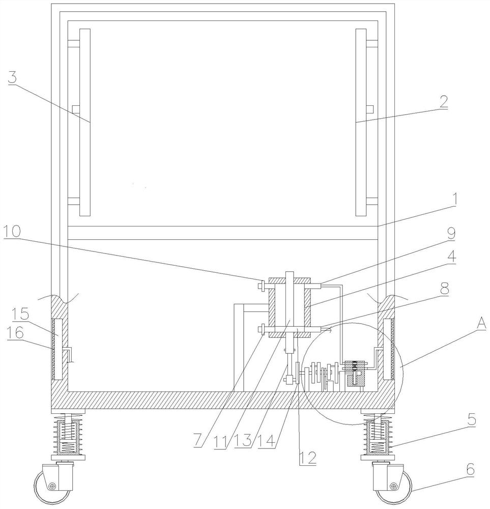
[0028] see Figure 1~5 , in Embodiment 1 of the present invention, an intelligent computer network chassis includes a box body 1, an air jet plate 2 and an air suction plate 3 fixedly arranged on both sides inside the box body 1, and air suction plates 3 fixedly installed on both sides of the box body 1 respectively. Two elastic filter screens 16 and intermittent cooling mechanism in the two air intake chambers 15;

[0029] Among them, the intermittent cooling mechanism includes a cylinder 4 fixedly installed inside the box body 1, the upper sides of the cylinder 4 are provided with a B exhaust port 9 and a B exhaust port 10, and the lower side of the lower part is provided with an A exhaust port 7 and an A intake port. Air port 8, wherein A exhaust port 7 is communicated with jet plate 2 through pipelines, B exhaust port 10 is communicated with suction plate 3 through pipelines; B exhaust port 9 and A air inlet 8 are respectively connected with reversing valve assembly The C...

Embodiment 2

[0033] see Figure 1~5 The main difference between this embodiment 2 and embodiment 1 is that the piston 12 is fixedly installed in the middle of the piston rod 11, and the two ends of the piston rod 11 are set through the upper and lower ends of the cylinder 4. This setting makes the upper and lower spaces of the cylinder 4 in the The consistency is ensured when switching, so as to maintain the stability of the internal pressure of the box body 1 .

[0034]A connecting rod 13 is mounted on the driving rod of the piston 12, and one end of the connecting rod 13 is hinged with the A driving disc 14. The driving rod is arranged eccentrically. This setting is convenient for the driving connecting rod 13 to drive the A driving disc 14 to move up and down. .

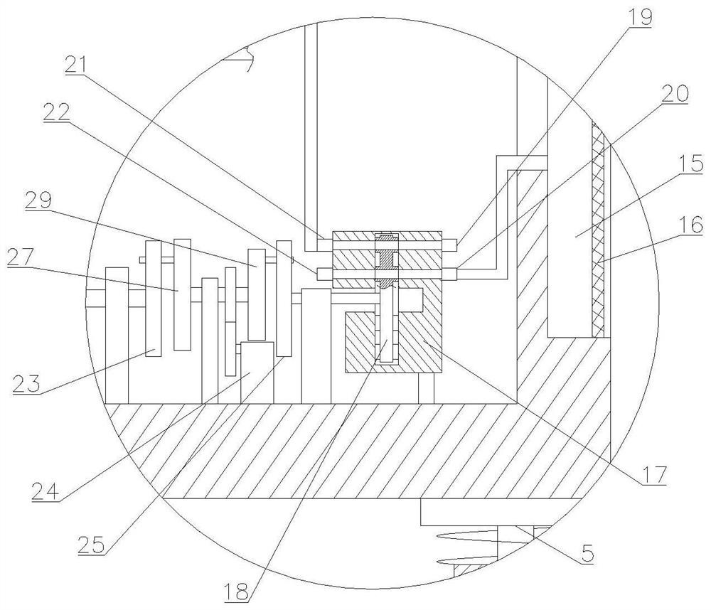
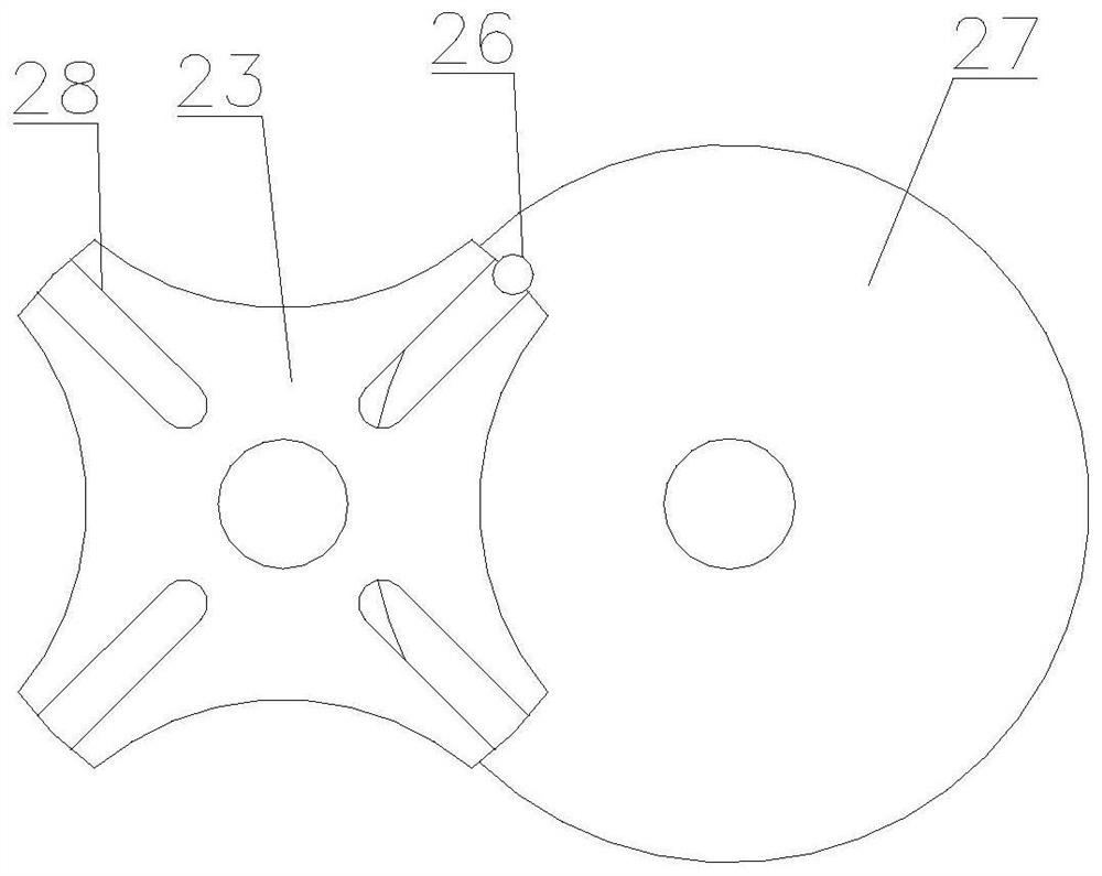
[0035] Described intermittent component comprises A drive dial 27, A drive dial 29 and the A sheave 23 that is coaxially arranged with A drive plate 14; Described A drive dial 29 and A drive dial 27 are coaxially arranged, an...


PUM


Abstract

The invention discloses an intelligent computer network box, which relates to the technical field of computer equipment; it comprises a box body, an air jet plate and an air suction plate fixedly arranged on both sides inside the box body, and two intake plates fixedly installed on both sides of the box body respectively. Two elastic filter screens and intermittent cooling mechanism in the air cavity; also includes the intermittent parts that drive the piston rod inside the cylinder to move up and down intermittently, the piston rod is equipped with a piston, and the reversing valve assembly includes a fixed installation inside the box The connecting block and the reversing valve block that is rotated inside the connecting block, the intermittent parts are double output ends, one end of which is connected to the reversing valve block, and the reversing valve block is provided with four stations, two of which A station cuts off the connecting block, and the two stations are arranged at intervals. The invention realizes avoiding the self-cleaning of the filter net and is convenient to use.

Description

technical field [0001] The invention relates to the technical field of computer equipment, in particular to an intelligent computer network case. Background technique [0002] With the development of the IT industry, computers and communication equipment have penetrated more and more into every corner of social life. At present, a large number of computers and communication equipment are generally installed in the network chassis, and all kinds of equipment are arranged through the network chassis, which plays a role of safety protection for the equipment installed in it, and at the same time, the stacking arrangement can save the floor space , and it can also make the cables between each device orderly, neat and beautiful, which is convenient for system maintenance. [0003] Since various network devices are installed inside the chassis, the network devices will generate heat during use, and a heat dissipation system needs to be installed. The heat dissipation system in th...

Claims


Application Information

Patent Timeline
Patent Type & Authority Patents(China)
IPC IPC(8): H05K5/02
CPCH05K5/0213H05K5/0217
Inventor 李文星姜乐明
Owner HANGZHOU FENGHENG ELECTROMECHANICAL
Learn More