Cutting board grooving device

A technology for cutting grooves and chopping boards, which is applied to clamping devices, feeding devices, slotting machines, etc., can solve the problems of long time consumption, low work efficiency, and manpower consumption, so as to save manpower, improve work efficiency, and operate simple effect

Active Publication Date: 2021-06-29
陈玲佳
View PDF0 Cites 0 Cited by
  • Summary
  • Abstract
  • Description
  • Claims
  • Application Information

AI Technical Summary

Problems solved by technology

[0006] In order to overcome the disadvantages of the above-mentioned method that it takes a long time to operate, the work efficiency is low, and it needs to be operated by a manual hand-held grooving device and an anvil board, which is relatively labor-intensive, the technical problem to be solved by the present invention is to provide a A cutting board grooving device that can improve work efficiency and save manpower when grooving

Method used


Image

  • Cutting board grooving device
  • Cutting board grooving device
  • Cutting board grooving device

Examples


Embodiment 1

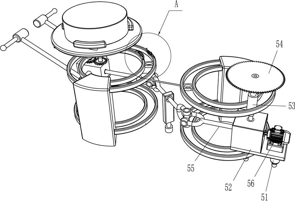
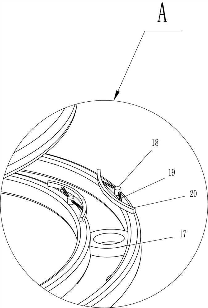
[0027] A cutting board grooving device, such as Figure 1-5 As shown, it includes a workbench 1, a mounting plate 2 and an annular slide rail 3, the left and right sides of the top of the workbench 1 are connected with the installation plate 2, the upper and lower sides of the installation plate 2 are connected with the annular slide rail 3, and there are also clips Tightening device 4, cutting device 5, second rotating shaft 6, bearing housing 7, first rotating rod 8, second rotating rod 9, multi-directional rotating shaft 10, push rod 11 and blanking box 12, the right mounting plate 2 A clamping device 4 is provided between the two circular slide rails 3, a cutting device 5 is provided between the two circular slide rails 3 on the left mounting plate 2, and a second rotating shaft 6 is rotatably connected in the middle of the top of the workbench 1. The second rotating shaft 6 is connected with a bearing seat 7, the upper part of the bearing seat 7 is rotatably connected wit...

Embodiment 2

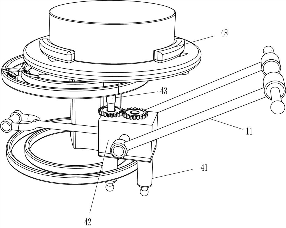
[0032] On the basis of Example 1, such as Figure 6-7 As shown, it also includes a third rotating shaft 13, a fourth rotating shaft 14, a second bevel gear 15 and a circular gear 16, and the first mounting box 42 is rotationally connected with the third rotating shaft 13, and the third rotating shaft 13 and the second rotating rod 9 connection, the upper part of the first installation box 42 is rotatably connected with the fourth rotating shaft 14, the fourth rotating shaft 14 and the third rotating shaft 13 are connected with the second bevel gear 15, the two second bevel gears 15 mesh with each other, the fourth A circular gear 16 is connected to the top of the rotating shaft 14 and the first rotating slide bar 43 , and the two circular gears 16 mesh with each other.

[0033] The first rotating shaft 55 also drives the first rotating rod 8 to rotate through the multidirectional rotating shaft 10 when rotating, and the first rotating rod 8 rotates to drive the second rotating...


PUM


Abstract

The invention relates to a grooving device, in particular to an anvil board grooving device. The technical problem to be solved by the present invention is how to design a chopping board grooving device that can improve work efficiency and save manpower when grooving. The present invention provides such a chopping board grooving device, comprising: a workbench, the two sides of the top of which are connected with mounting plates, and the upper and lower sides of the mounting plate are connected with annular slide rails; the clamping device is arranged on one side between the two ring-shaped slide rails on the mounting plate; the cutting device is arranged between the two ring-shaped slide rails on the other side of the mounting plate. The present invention clamps the chopping board by a clamping device, and after clamping the chopping board, slots the chopping board through a cutting device, thereby achieving the effect of slotting the chopping board.

Description

technical field [0001] The invention relates to a grooving device, in particular to an anvil board grooving device. Background technique [0002] A chopping board is a wooden board that is placed on the table to prevent damage to the table when cutting vegetables. The colloquial language is called a chopping board, and the written language is called a chopping board. In the past, cutting boards were mainly made of wood, but because they are easy to wear and tear, most of them are cast with plastic recently. In order to avoid cracking caused by improper storage, the cutting board should not be soaked in water or exposed to sunlight for a long time. When the chopping block is made, it is necessary to make grooves on the outer arc surface of the chopping block, so as to facilitate the fitting of steel rings on the outside of the chopping block. [0003] At present, the method of grooving the cutting board is usually to manually use the grooving device to move along the outer...

Claims


Application Information

Patent Timeline
Patent Type & Authority Patents(China)
IPC IPC(8): B27B5/02B27B25/00B27B29/02B27F5/00
CPCB27B5/02B27B25/00B27B29/02B27F5/00
Inventor 刘娟梅
Owner 陈玲佳
Why Eureka
Try Eureka