
Clamping and slotting device for a birdcage

A technology of birdcages and shafts, applied in slotting machines, mortising machines, sugarcane machining, etc., can solve the problems of high technical requirements and manpower consumption, and achieve the effect of simple operation and labor saving

Active Publication Date: 2021-12-07
罗勇鹏
View PDF5 Cites 0 Cited by
  • Summary
  • Abstract
  • Description
  • Claims
  • Application Information

AI Technical Summary

Problems solved by technology

[0006] In order to overcome the disadvantages of the above-mentioned method that consumes more manpower during operation, and requires manual judgment to adjust the slotting position during operation, and requires high technical requirements for workers, the technical problem to be solved by the present invention is to provide a Capable of saving manpower and easy to operate the snap-in slotting device of the bird cage

Method used


Image

  • Clamping and slotting device for a birdcage
  • Clamping and slotting device for a birdcage
  • Clamping and slotting device for a birdcage

Examples


Embodiment 1

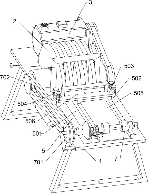
[0025] A kind of locking and slotting device of birdcage, such as Figure 1-2 As shown, it includes a base 1, a tooth saw 2, a motor 3 and a rotating shaft 4. The rear side of the top of the base 1 is rotatably connected to the rotating shaft 4. The rotating shaft 4 is connected to the tooth saw 2. The motor 3 is installed on the rear side of the top of the base 1. The output shaft of 3 is connected with the rotating shaft 4 by belt and pulley transmission, and also includes adjustment mechanism 5 and limit mechanism 6, and base 1 front side is provided with adjustment mechanism 5, and base 1 middle part is provided with limit mechanism 6.

[0026] The adjustment mechanism 5 includes a guide rod 502, a top plate 503, a pressure spring 504, a fixed plate 505 and a block 507. The front side of the top of the base 1 has a chute 501, and the middle part of the top of the base 1 is connected with a guide rod 502 on both sides. A top plate 503 is slidably connected between the side ...

Embodiment 2

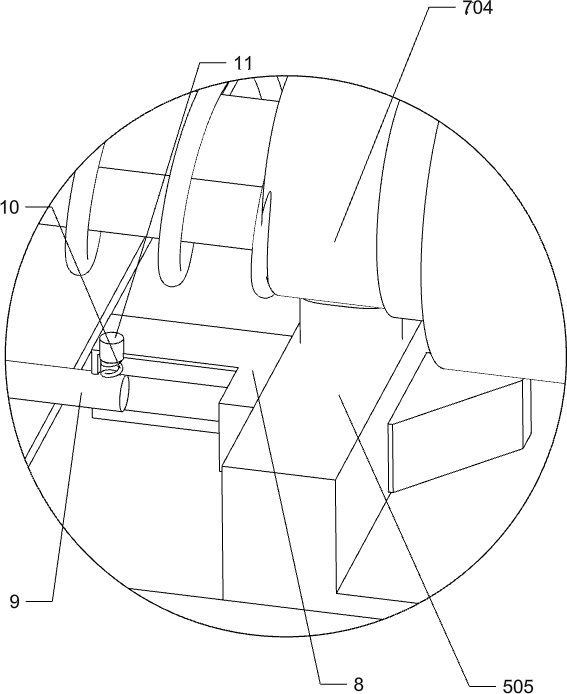
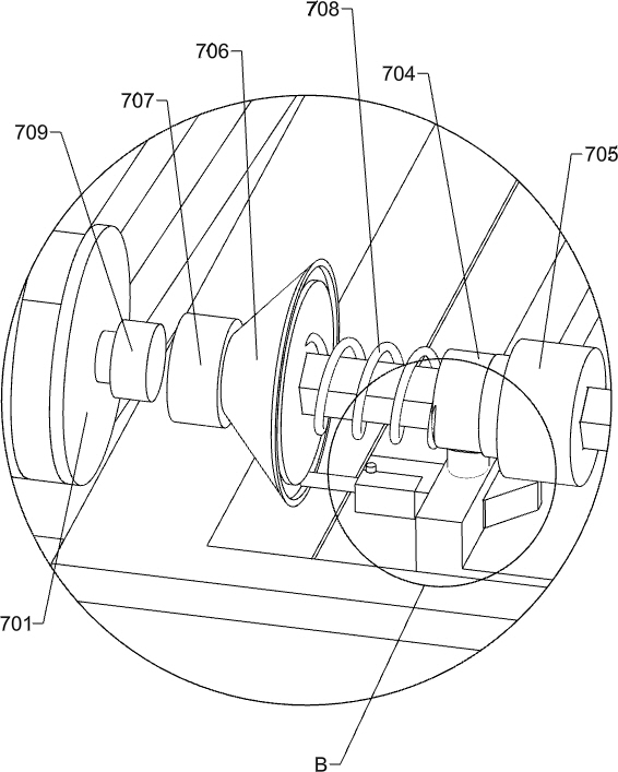
[0030] On the basis of Example 1, such as Figure 1-4 As shown, it also includes a transmission mechanism 7 and a clamping mechanism. The transmission mechanism 7 is provided on the front side of the top of the base 1 , and a clamping mechanism is provided between the fixed plate 505 and the transmission mechanism 7 .

[0031] Transmission mechanism 7 comprises sprocket 701, chain 702, hexagonal bar 703, axle sleeve 704, roller 705, cone 706, first magnet 707, back-moving spring 708 and second magnet 709, base 1 top front side and rotating shaft 4 are connected with a sprocket 701, a chain 702 is wound between the two sprockets 701, a hexagonal rod 703 is connected to the right front side of the top of the base 1, and a shaft is connected to the left and right sides of the top front of the fixed plate 505. Sleeve 704, shaft sleeve 704 and hexagonal rod 703 rotate and cooperate, hexagonal rod 703 and shaft sleeve 704 slide fit, hexagonal rod 703 left and right sides are sliding...


PUM


Abstract

The invention relates to a slotting device, in particular to a clamping slot slotting device for a birdcage. The technical problem to be solved by the present invention is how to design a birdcage locking and slotting device that can save manpower during operation and is easy to operate. The present invention provides such a clamping and slotting device for a birdcage, comprising: a base, a rotating shaft connected to the top side in a rotational manner, and a tooth saw connected to the rotating shaft; a motor installed on the top side of the base close to the rotating shaft , the output shaft of the motor is connected to the rotating shaft through transmission; the adjustment mechanism is arranged on the other side of the base; the limit mechanism is arranged in the middle of the base. In the invention, the adjustment mechanism, the limit mechanism and the tooth saw cooperate to operate to slot the bamboo slices, so as to achieve the effect of slotting the bamboo slices.

Description

technical field [0001] The invention relates to a slotting device, in particular to a clamping slot slotting device for a birdcage. Background technique [0002] The birdcage is the main environment for watching birds to carry out activities and inhabit. "If a worker wants to be good at his work, he must first sharpen his tools." Whether the bird-raising utensils are applicable or not is one of the keys to raising a good watching bird. Therefore, only by preparing suitable birdcages and other accessories can the birds be kept healthy and lively, singing freely, and suitable for viewing. According to different body shapes and habits, birdcages are divided into many types. The birdcage usually needs to be made by using the snap-on technique, and the bamboo slices used to make the birdcage usually need to be grooved during the manufacture. [0003] At present, the way of slotting the bamboo slices is usually to manually place the bamboo slices on the slotting equipment, and t...

Claims


Application Information

Patent Timeline
Patent Type & Authority Patents(China)
IPC IPC(8): B27J1/00B27F5/02B27B5/02B27B5/22B27B5/29B27B29/00
CPCB27B5/02B27B5/22B27B5/29B27B29/00B27F5/02B27J1/00
Inventor 唐友志罗勇鹏
Owner 罗勇鹏
Learn More