Energy storage control method and system for reducing peak-valley difference of power grid load

A power grid load and energy storage control technology, applied in the direction of AC network load balancing, can solve problems such as poor regularity, power grid transformer overload, reverse transmission, etc., to ensure safe and stable operation, prevent transformer overload, and reduce power grid peaks and valleys poor effect

Inactive Publication Date: 2020-07-14
STATE GRID ECONOMIC TECH RES INST CO +3
View PDF4 Cites 0 Cited by
  • Summary
  • Abstract
  • Description
  • Claims
  • Application Information

AI Technical Summary

Problems solved by technology

However, renewable energy is greatly affected by factors such as environment, climate and temperature.
This makes the amount of electricity generated by renewable energy sources over a period of time unstable and less regular
Renewable energy access to the grid usually adopts distributed power generation. The power output of the distributed power source has the chara

Method used


Image

  • Energy storage control method and system for reducing peak-valley difference of power grid load
  • Energy storage control method and system for reducing peak-valley difference of power grid load
  • Energy storage control method and system for reducing peak-valley difference of power grid load

Examples


Embodiment 1

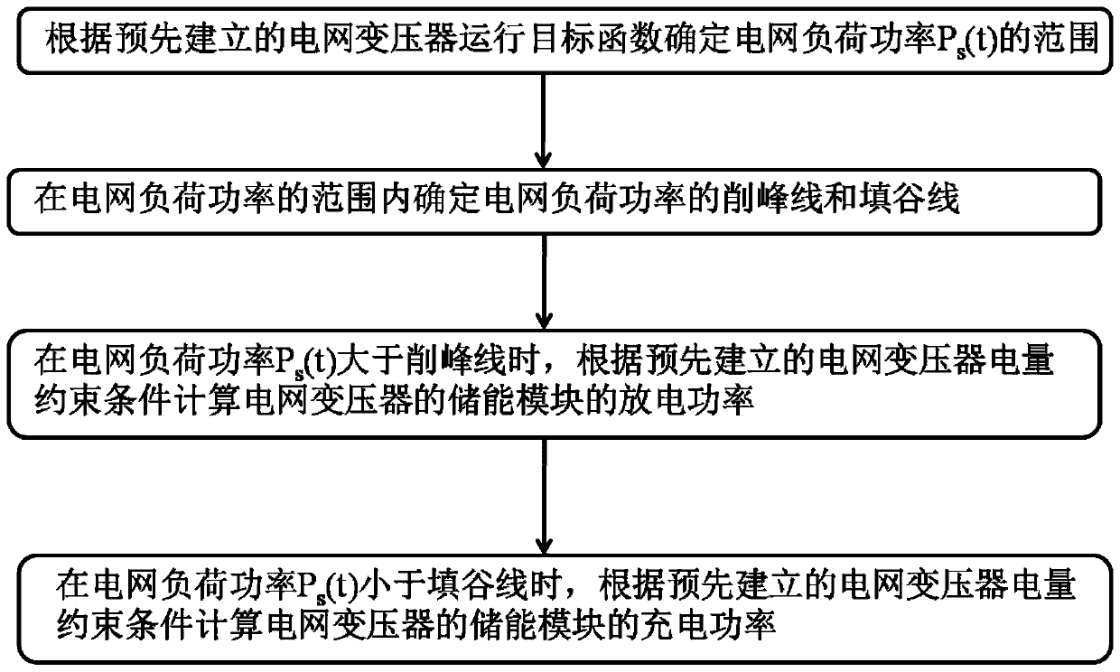
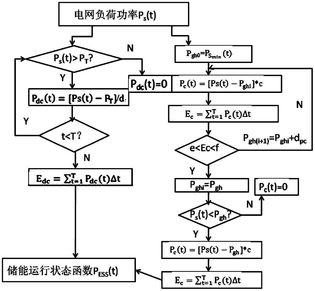
[0035] This embodiment discloses an energy storage control method for reducing the peak-to-valley load difference of the power grid, such asfigure 1 shown, including the following steps:

[0036] Determine the grid load power P according to the pre-established grid transformer operation objective function s the extent of (t);

[0037] Determine the peak-shaving line and the valley-filling line of the grid load power within the range of the grid load power;

[0038] In the grid load power P s (t) when greater than the peak-shaving line, calculate the discharge power of the energy storage module of the grid transformer according to the pre-established grid transformer power constraints;

[0039] In the grid load power P s When (t) is less than the valley filling line, calculate the charging power of the energy storage module of the grid transformer according to the pre-established grid transformer power constraints.

[0040] This method uses the energy storage module to shif...

Embodiment 2

[0060] Based on the same inventive concept, this embodiment discloses an energy storage module control system that reduces the peak-to-valley difference in power grid load, including:

[0061] The grid load power range determination module is used to determine the grid load power P according to the pre-established grid transformer operation objective function s the extent of (t);

[0062] The peak-shaving and valley-filling module is used to determine the peak-shaving line and valley-filling line of the grid load power within the range of the grid load power;

[0063] The discharge power calculation module is used for the grid load power P s (t) When it is greater than the peak-shaving line, calculate the discharge power of the energy storage module of the grid transformer according to the pre-established grid transformer power constraints;

[0064] Charging power calculation module, used for load power P of the grid s When (t) is less than the valley filling line, calculat...

Embodiment 3

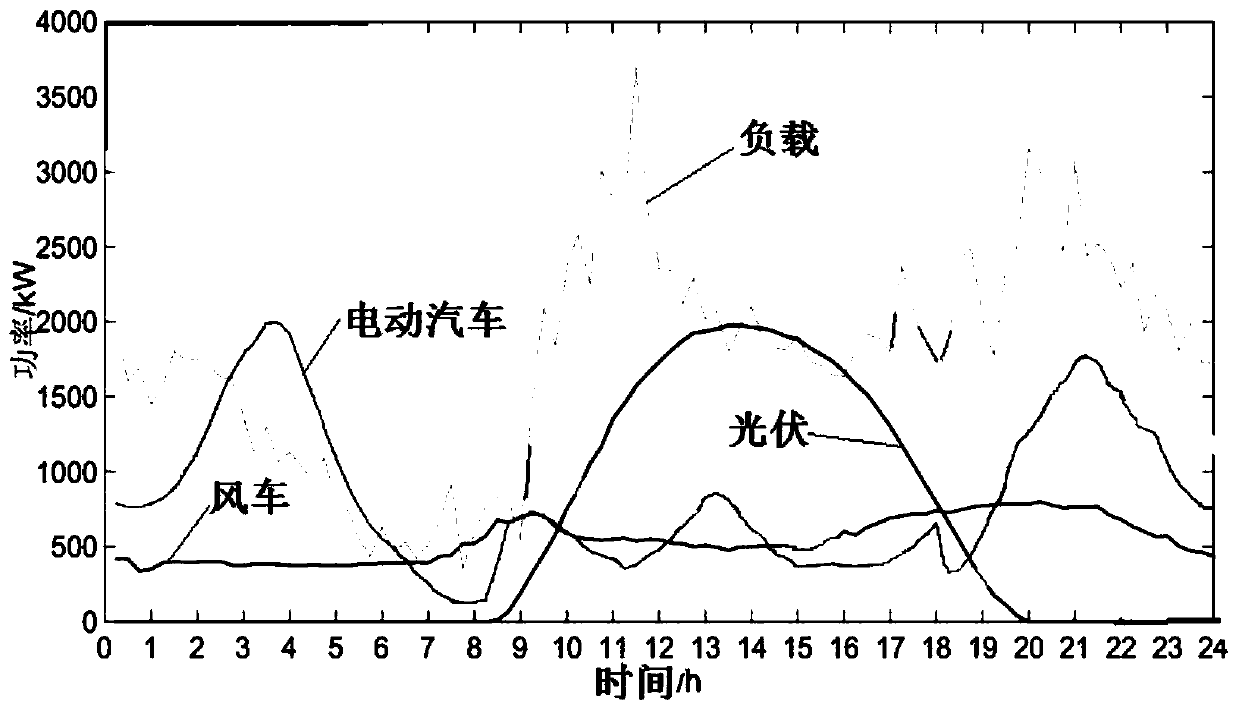
[0066] In this example, the load power data actually collected in a typical spring day in a certain area is used to calculate according to the method in Embodiment 1, which is used to verify the practicability and effect of the method and device of the present invention.

[0067] Such as image 3As shown, the wind force in this area is strong in spring, so the output level of wind power is relatively high, and the wind power output curve is relatively stable. At the same time, the typical day is sunny, so the photovoltaic output is relatively large, and the typical daily distributed power output and load curve is obtained.

[0068] Such as Figure 4 As shown, after electric vehicles are connected to the grid, the grid load changes greatly: from 0:00 to 8:00, the charging load of electric vehicles is relatively large, the photovoltaic output is low, and the load level of the distribution network is not high. During the period from 11:00 to 18:00, the output of distributed powe...


PUM


Abstract

The invention relates to an energy storage control method and system for reducing the peak-valley difference of a power grid load. The method comprises the following steps: determining the range of the power grid load power Ps(t) according to a pre-established power grid transformer operation target function; determining a peak clipping line and a valley filling line of the power grid load power in the range of the power grid load power; when the power grid load power Ps(t) is greater than the peak clipping line, calculating the discharge power of an energy storage module of the power grid transformer according to a pre-established power grid transformer electric quantity constraint condition; when the power grid load power Ps(t) is smaller than the valley fill line, calculating the charging power of an energy storage module of the power grid transformer according to a pre-established power grid transformer electric quantity constraint condition. Peak-valley difference of a power gridis reduced through the energy storage module, overload of a transformer is relieved, and power reverse transmission from the power grid to a main grid is reduced.

Description

technical field [0001] The invention relates to an energy storage control method and system for reducing the peak-to-valley difference of power grid load, and belongs to the technical field of electric power regulation. Background technique [0002] With the development of renewable energy and grid technology, the proportion of renewable energy integrated into the grid continues to increase. As of 2016, the installed capacity of renewable energy power generation in my country was 570 million kilowatts. However, renewable energy is greatly affected by factors such as the environment, climate and temperature. This makes the amount of electricity generated by renewable energy sources over a period of time unstable and less regular. Renewable energy access to the grid usually adopts distributed power generation. The power output of the distributed power source has the characteristics of intermittent, random, and volatility, which makes the power source nature, access mode, vol...

Claims


Application Information

Patent Timeline
IPC IPC(8): H02J3/28
CPCH02J3/28
Inventor 金强张红斌李红军李军徽吴志力钱康周恒宇赵波东哲民蒋科杨露露丁羽頔马唯婧冯明灿汪湘晋
Owner STATE GRID ECONOMIC TECH RES INST CO
Why Eureka
Try Eureka