
Insulation can for blade maintenance

A technology for incubators and blades, which is applied in aircraft maintenance, devices for coating liquid on the surface, workpiece clamping devices, etc., can solve the problems of rotor blade accident hazards, affect flight safety, and low work efficiency, and achieve convenient Automatically adjust and lock, facilitate proofreading and installation, and improve installation efficiency

Inactive Publication Date: 2020-07-17
北京博奥瑞科技有限公司
View PDF0 Cites 2 Cited by
  • Summary
  • Abstract
  • Description
  • Claims
  • Application Information

AI Technical Summary

Problems solved by technology

[0002] Helicopter rotor blade in-situ rapid repair equipment is mainly used for rapid repair of the blade in the original state when there is a glue-opening defect in the iron coating on the leading edge of the helicopter blade. The helicopter rotor blade is made of composite materials, and the leading edge of the blade is The iron-clad protective structure is adopted. Due to the influence of many physical conditions such as impact, pressure, vibration, deformation, and damp heat during long-term work, the blades are prone to problems such as glue separation, warping, warping, debonding, and deformation, resulting in rotor blades. Hidden dangers of leaf accidents. At present, our army conducts a large number of military drills. Helicopters are frequently used in drills. After the blades of the helicopters are defective, they need to be repaired quickly to meet military needs. If they are not repaired in time, it will affect flight safety and even lead to accidents. Occurrence, the glue opening of the iron-clad protective structure at the leading edge of the helicopter rotor blade is the most common fault defect. The current maintenance status is to apply glue to the damaged part of the glue and repair it under normal temperature and pressure conditions. The bonding and curing time takes about 7 days. The working efficiency is low. In order to improve the working efficiency and realize the rapid repair in different environments, therefore, an incubator for repairing the propeller is needed to repair the propeller

Method used


Image

  • Insulation can for blade maintenance
  • Insulation can for blade maintenance
  • Insulation can for blade maintenance

Examples


Embodiment Construction

[0031] The following will clearly and completely describe the technical solutions in the embodiments of the present invention with reference to the accompanying drawings in the embodiments of the present invention. Obviously, the described embodiments are only some, not all, embodiments of the present invention. Based on the embodiments of the present invention, all other embodiments obtained by persons of ordinary skill in the art without making creative efforts belong to the protection scope of the present invention.

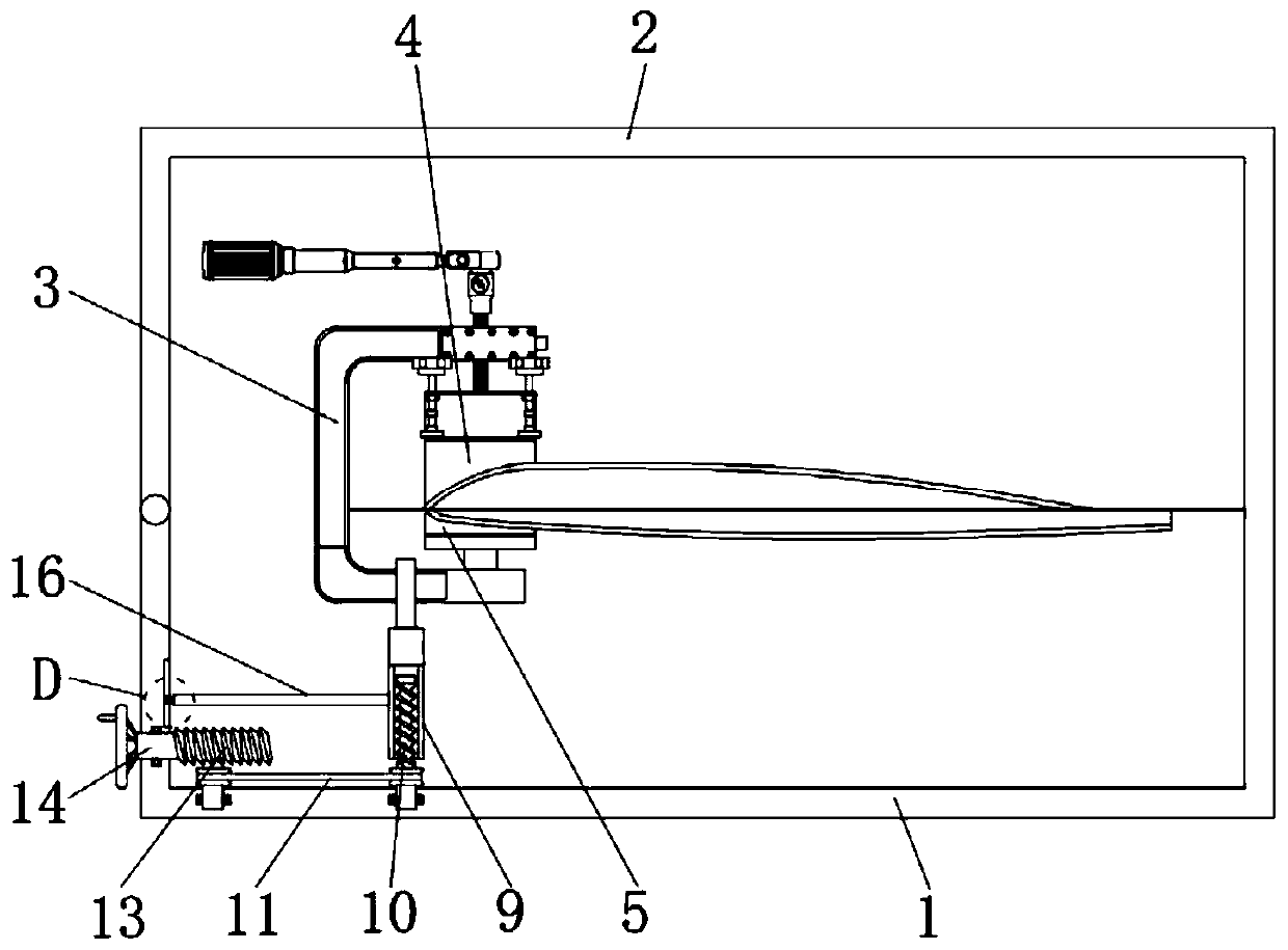
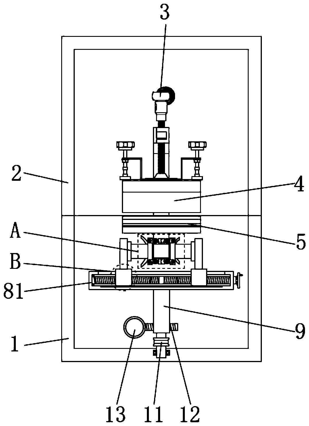
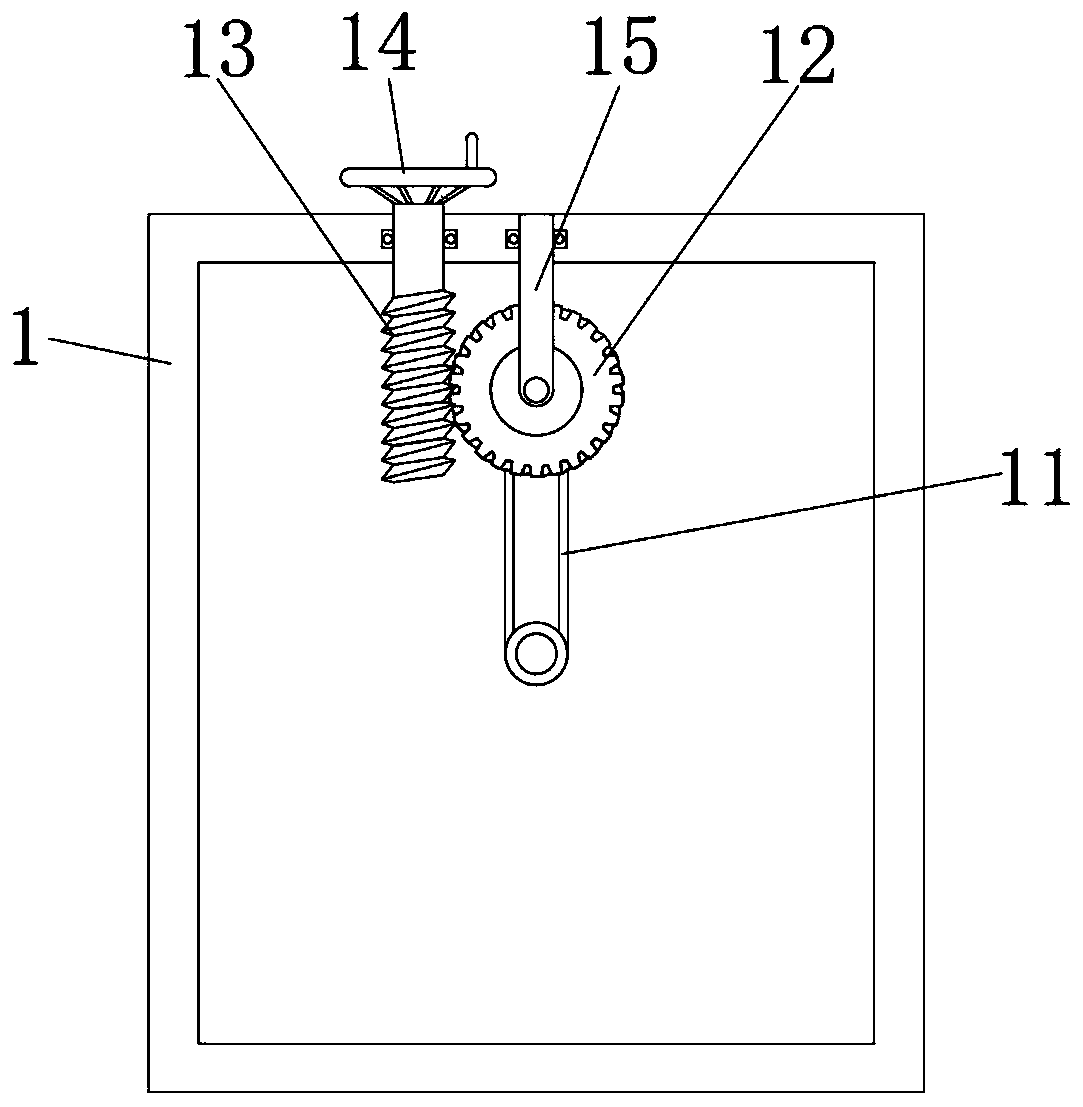
[0032] Please refer to Figure 1-10, the present invention provides a technical solution: an incubator for blade maintenance, including a bottom cover 1, a top cover 2, a support frame 3, an upper clamp 4 and a lower clamp 5, and the top of the bottom cover 1 is hingedly mounted with a top cover 2 , and the inside of the top cover 2 is equipped with a support frame 3, and the inner top end of the support frame 3 is equipped with an upper clamp 4, and the inner...


PUM


Abstract

The invention discloses an insulation can for blade maintenance. The insulation can comprises a bottom cover, a top cover, a support frame, an upper clamp and a lower clamp, wherein the top cover is hinged to the top end of the bottom cover, and the support frame is arranged in the top cover; the insulation can for blade maintenance is provided with clamping blocks and first clamping rods, so thatthe usable range of a clamping mechanism is conveniently increased, and the practicability of the clamping mechanism is increased; the insulation can for blade maintenance is provided with a slidingsleeve and a second clamping rod, so that the clamping mechanism is conveniently driven to fixedly clamp the support frame; the insulation can for blade maintenance is provided with a sliding rod anda third rotating rod, so that the upper clamp and the lower clamp are conveniently matched with arc openings in the surface of the bottom cover and the surface of the top cover in order to conveniently and quickly carry out check and installation; the insulation can for blade maintenance is provided with a turbine and a worm, so that the sliding rod can conveniently slide up and down on the surface of the third rotating rod in order to conveniently carry out check; and the insulation can for blade maintenance is provided with a sealing gasket and a third spring, so that the insulation can is more tightly attached to the surface of a blade.

Description

technical field [0001] The invention relates to the technical field of blade maintenance and processing, in particular to an incubator for blade maintenance. Background technique [0002] Helicopter rotor blade in-situ rapid repair equipment is mainly used for rapid repair of the blade in the original state when there is a glue-opening defect in the iron coating on the leading edge of the helicopter blade. The helicopter rotor blade is made of composite materials, and the leading edge of the blade is The iron-clad protective structure is adopted. Due to the influence of many physical conditions such as impact, pressure, vibration, deformation, and damp heat during long-term work, the blades are prone to problems such as glue separation, warping, warping, debonding, and deformation, resulting in rotor blades. Hidden dangers of leaf accidents. At present, our army conducts a large number of military drills. Helicopters are frequently used in drills. After the blades of the hel...

Claims


Application Information

Patent Timeline
Patent Type & Authority Applications(China)
IPC IPC(8): B29C35/02B05D3/00B23P6/00B25B11/00B64F5/40
CPCB05D3/007B23P6/002B25B11/00B29C35/002B29C35/02B64F5/40
Inventor 邴泽张松王波李伯韬
Owner 北京博奥瑞科技有限公司
Learn More