Form recognition method, device, electronic device, storage medium
A recognition method and table technology, applied in the field of image recognition, can solve the problems of inability to accurately identify table data, poor robustness of table recognition, and inability to accurately identify tables, etc.
- Summary
- Abstract
- Description
- Claims
- Application Information
AI Technical Summary
Problems solved by technology
Method used
Image
Examples
Embodiment 1
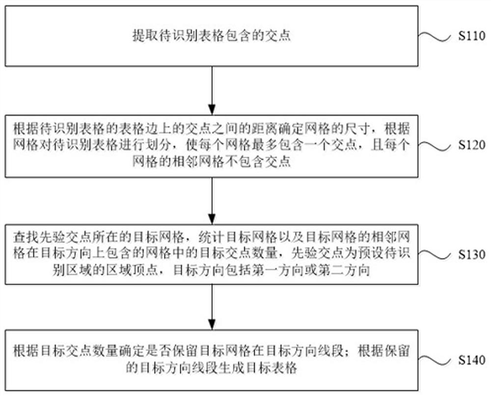
[0025] figure 1 It is a schematic flow chart of a form recognition method provided in Embodiment 1 of the present application. This method is applicable to the situation of recognizing forms in OCR technology. The method can be executed by an electronic device used to recognize an image. The electronic device can be a personal computer, a tablet computer or smartphone, etc., the method includes:
[0026] Step 110, extract the intersection points contained in the table to be recognized.
[0027] Wherein, the table to be recognized includes a line segment in the first direction and a line segment in the second direction, the line segment in the first direction intersects the line segment in the second direction, and the intersection point is the point where the line segment in the first direction intersects the line segment in the second direction.
[0028] The table to be recognized is located in the currently processed image. In the scenario used in this application, the use...
Embodiment 2
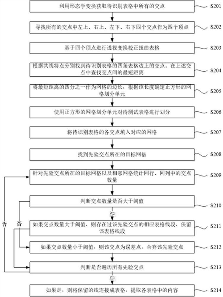
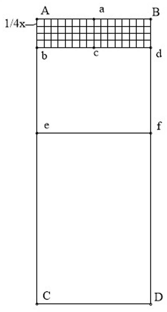
[0051] figure 2 The schematic flow diagram of the form recognition method provided in Embodiment 2 of the present application, as an example of the above embodiment, in this example, the form to be recognized is a rectangular form, such as image 3 As shown, the table to be recognized has four vertices, namely vertex A, vertex B, vertex C and vertex D, vertex A and vertex B constitute the table edge AB, vertex B and vertex D constitute the table edge BD, vertex C and vertex D A table edge CD is formed, and vertex A and vertex C form a table edge AC. The edge of the table includes intersection point a, intersection point b, intersection point c, intersection point d, intersection point e and intersection point f. Vertex A, Vertex B, Vertex C, and Vertex D can also be considered intersection points. When identifying the form to be extracted, the method may be implemented through the following steps:
[0052] Step 201, using morphological transformation to obtain all intersec...
Embodiment 3
[0078] Figure 4 The structural diagram of the form recognition device provided in Embodiment 3 of the present application, the device may be located in an electronic device for recognizing images, and the electronic device may be a personal computer, a tablet computer, or a smart phone, etc., and the device includes: an intersection point extraction module 310, a network grid division module 320 , target grid intersection statistics module 330 and target table generation module 340 . in:
[0079] The intersection point extraction module 310 is used to extract the intersection points contained in the table to be recognized, the table to be recognized includes a line segment in the first direction and a line segment in the second direction, the line segment in the first direction and the line segment in the second direction intersect, and the intersection point is a line segment in the first direction the point where the line segment intersects the line segment in the second d...
PUM
 Abstract
Description
Claims
Application Information
 - R&D
- Intellectual Property
- Life Sciences
- Materials
- Tech Scout
- Unparalleled Data Quality
- Higher Quality Content
- 60% Fewer Hallucinations
Browse by: Latest US Patents, China's latest patents, Technical Efficacy Thesaurus, Application Domain, Technology Topic, Popular Technical Reports.
© 2025 PatSnap. All rights reserved.Legal|Privacy policy|Modern Slavery Act Transparency Statement|Sitemap|About US| Contact US: help@patsnap.com


