Six-phase rectification generator winding coil inserting structure and coil inserting method

A rectifier generator, wire structure technology, applied in the shape/style/structure of winding insulation, the shape/style/structure of winding conductor, and the manufacture of motor generators, etc. Problems such as raised ends

Pending Publication Date: 2020-07-17
KUNGFU SCI TECH CO LTD
View PDF0 Cites 0 Cited by
  • Summary
  • Abstract
  • Description
  • Claims
  • Application Information

AI Technical Summary

Problems solved by technology

[0003] The winding has six phases, and the coils are more and more complicated than ordinary three-phase motors, and there are many lead-out wires from the coils, which makes it difficult to embed the wires. One phase and one phase embed the wires, which will cause the ends of the coils to rise, the ends of the windings cannot be shaped, and the windings are loose and messy.

Method used


Image

  • Six-phase rectification generator winding coil inserting structure and coil inserting method
  • Six-phase rectification generator winding coil inserting structure and coil inserting method
  • Six-phase rectification generator winding coil inserting structure and coil inserting method

Examples


Embodiment 1

[0034] Embodiment 1: A six-phase rectifier generator winding embedded wire structure

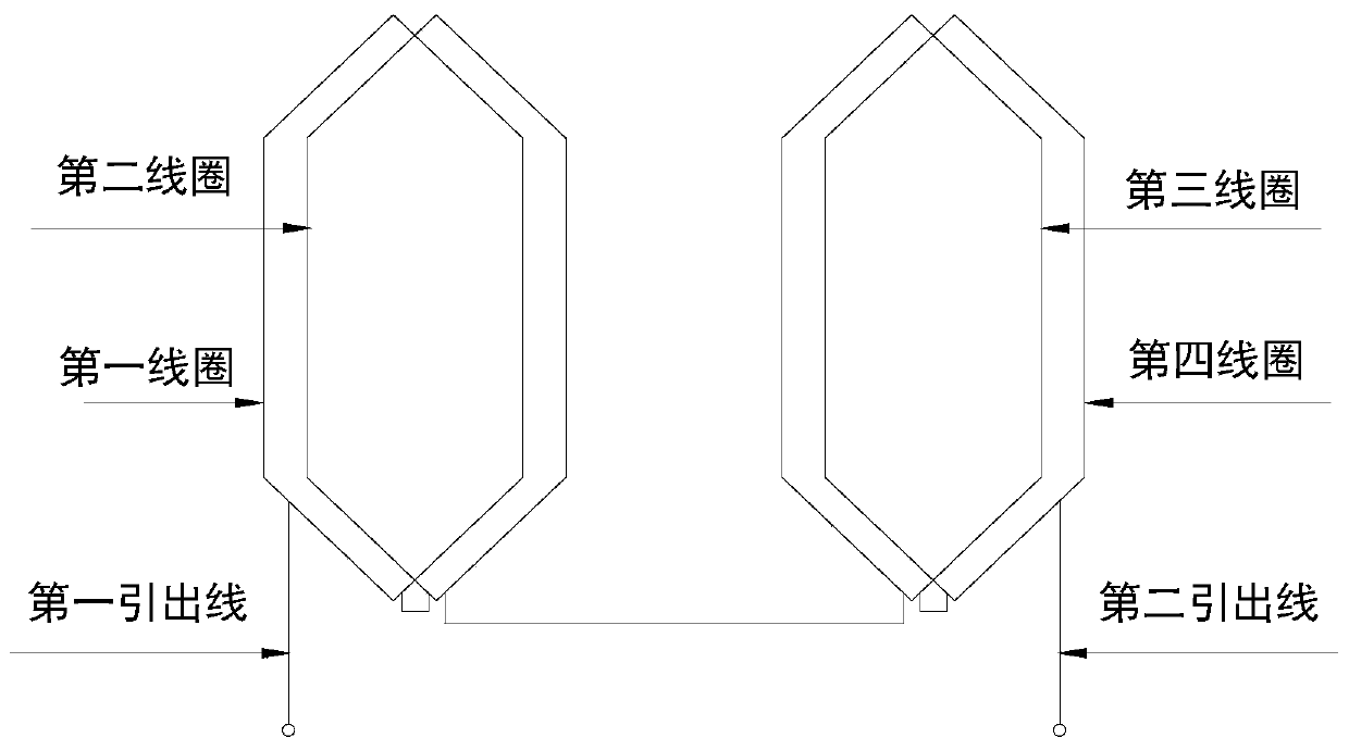
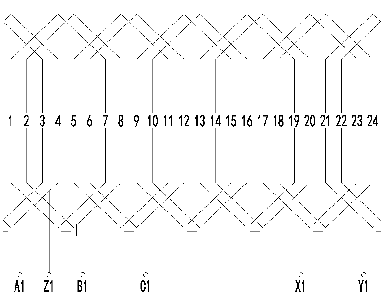
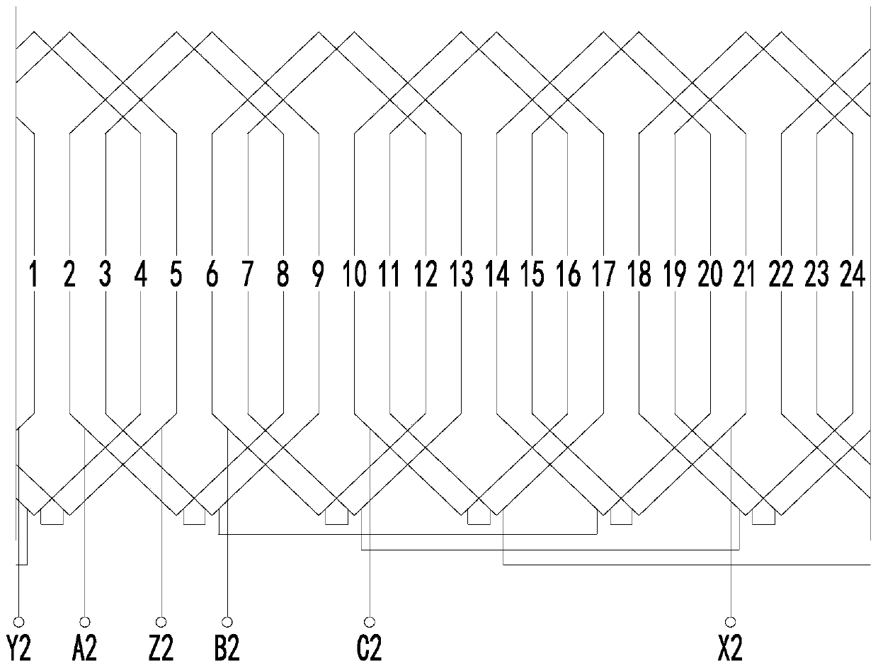
[0035] like Figure 1-3 As shown, an embodiment 1 of the present invention discloses a six-phase rectifier generator winding embedded wire structure including a stator iron core, the stator iron core is provided with a first three-phase winding and a second three-phase winding, and the first three-phase winding includes A1 Phase, B1 phase, C1 phase, the second three-phase winding includes A2 phase, B2 phase, C2 phase, the number of magnetic poles of the stator is 4; the first three-phase winding and the second three-phase winding The phase windings and the second three-phase windings are both distributed full-pitch single-layered windings; each of the first three-phase windings and the second three-phase windings includes a first coil, a second coil, and a third coil connected in series in sequence and the fourth coil; the pitches of the first coil, the second coil, the third coil and the f...

Embodiment 2

[0045] Embodiment 2: A six-phase rectifier generator winding embedding method

[0046] Embodiment 2 of the present invention also discloses a wire embedding method based on the six-phase rectifier generator winding wire embedding structure described in Embodiment 1, comprising the following steps:

[0047] Step 1: Send the first coil of the A1 phase and the first side of the second coil in the first three-phase winding into the No. 1 wire slot and No. 2 wire slot respectively, and at the same time put the A1 phase in the first three-phase winding. The edges of the first coil and the second coil of the second coil are lifted, leaving the No. 7 wire slot and No. 8 wire groove;

[0048] Step 2: Send the first coil of phase B1 and the first edge of the second coil in the first three-phase winding into the No. 5 wire slot and No. 6 wire slot respectively, and at the same time send the B1 phase of the first three-phase winding. The first coil and the second coil of the second coil ...


PUM


Abstract

The invention discloses a six-phase rectification generator winding coil inserting structure, which and relates to the technical field of motors, and. The structure comprises a stator core, the statorcore is provided with a first three-phase winding and a second three-phase winding, and the number of magnetic poles of a the stator is 4; wherein the difference between the first three-phase windingand the second three-phase winding is 30 degrees, and each phase winding of the three-phase windings comprises a first coil, a second coil, a third coil and a fourth coil which are sequentially connected in series; 24 wire slots are arranged along the circumference of the stator core, and a first ring edge of a phase coil in the first three-phase winding and a second ring edge of a phase coil inthe second three-phase winding are embedded in each wire slot. The invention further discloses a coil inserting method., coil Coil inserting of the front two-phase coil is completed by lifting while feeding, separating the coil from the groove and then falling into the groove, coil inserting of the subsequent coil edge can be completed only by connecting the previous inserted coil, coil insertingis simple and convenient, the winding is neat and compact, and the situation that the coil end is raised and cannot be shaped is avoided.

Description

technical field [0001] The invention relates to the technical field of electric motors, in particular to a wire-embedding structure and a wire-embedding method for a six-phase rectifier generator winding. Background technique [0002] With the development of the power system, more and more occasions require a generator system that can operate independently of the isolated grid. Since there is no phase difference in DC power, low-frequency oscillation will not occur, and the DC power transmission cost is low, the space is small, and the control is simple. Therefore, rectifier generators are required in many occasions. At present, six-phase rectifier generators use double Y-shift 30° windings, but there are also the following problems: [0003] The winding has six phases, and the coils are more and more complicated than ordinary three-phase motors, and there are many coil lead wires, which makes it difficult to insert the wire. One phase and one phase embedding will cause the ...

Claims


Application Information

Patent Timeline
Patent Type & Authority Applications(China)
IPC IPC(8): H02K3/28H02K3/12H02K3/34H02K15/085H02K11/04
CPCH02K3/12H02K3/28H02K3/34H02K11/046H02K15/085
Inventor 朱锡辉万滨滨俞业国徐志强
Owner KUNGFU SCI TECH CO LTD
Why Eureka
Try Eureka