Lead wire structure of a claw-pole miniature permanent magnet synchronous motor coil

A permanent magnet synchronous motor and claw-pole technology, applied in structural connections, electrical components, electromechanical devices, etc., can solve problems such as unfavorable transformation and upgrading, waste of raw materials, slow production efficiency, etc., to improve production efficiency, reduce production costs, Reduce the effect of lead-out lines

Active Publication Date: 2017-10-03
ZHAOQING LONGTOU ELECTRON & ELECTRIC
View PDF7 Cites 0 Cited by
  • Summary
  • Abstract
  • Description
  • Claims
  • Application Information

AI Technical Summary

Problems solved by technology

This method can only thread the lead wire by hand, and can only wind the enameled wire on the lead-out line by hand; it has the disadvantage of slow production efficiency, and only manual operation requires a lot of manpower. A certain burden is not conducive to the transformation and upgrading of enterprise automation and mechanization. At the same time, this method also uses a lot of tape, and needs to wrap the 80mm lead wire in the coil, resulting in waste of raw materials

Method used


Image

  • Lead wire structure of a claw-pole miniature permanent magnet synchronous motor coil
  • Lead wire structure of a claw-pole miniature permanent magnet synchronous motor coil
  • Lead wire structure of a claw-pole miniature permanent magnet synchronous motor coil

Examples


Embodiment 1

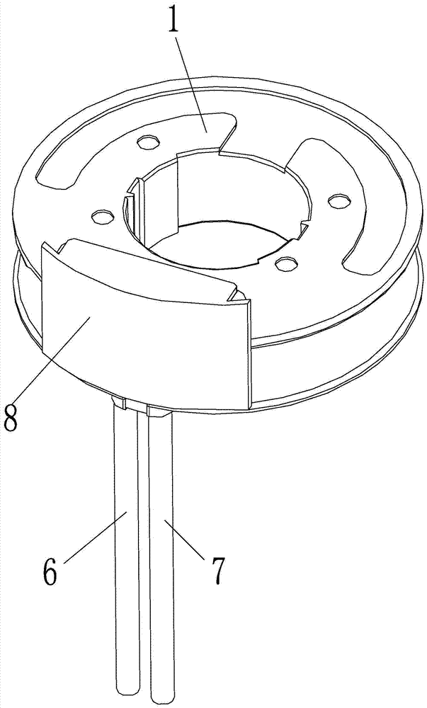
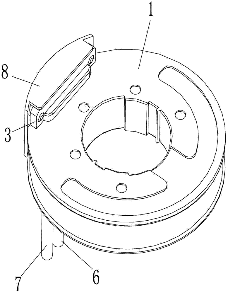
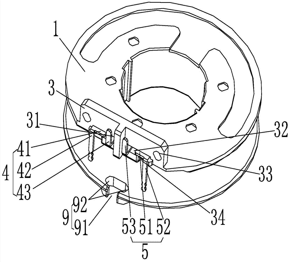
[0032] like Figure 1-6 As shown, the lead wire structure of a claw-pole miniature permanent magnet synchronous motor coil provided by the present invention includes a bobbin 1 wound with a coil 2 and a boss provided on the bobbin 1 for wiring 3; also includes the first connection terminal 4, the second connection terminal 5, the first wire 6, the second wire 7 and the protective cover 8;

[0033] The boss 3 is provided with a first mounting groove 31 and a second mounting groove 32;

[0034] The first connecting terminal 4 includes a first conductive installation piece 41 arranged horizontally, one end of the first installation piece 41 extends downwards in the vertical direction and a first electrode 42 is provided, and the other end of the first installation piece 41 extends vertically downwards. There is a first conductive connecting piece 43 extending vertically upward; the first mounting piece 41 is clamped in the first mounting groove 31;

[0035] The second connectin...

Embodiment 2

[0043] This embodiment is characterized in that: the first wire is fixedly connected to the first conductive connection piece by welding; the second wire is fixedly connected to the second conductive connection piece by welding. Others are the same as in Example 1.

Embodiment 3

[0045] The feature of this embodiment is that: the boss is provided with two clamping posts, and correspondingly, the protective cover is provided with two clamping holes; the two clamping posts of the boss are respectively inserted into the In the two clamping holes of the protective cover, a snap connection is realized between the protective cover and the boss. Others are the same as in Example 1.

[0046] Other examples:

[0047] The insulating partition is arranged on the protective cover, or the insulating partition is arranged on the boss. The protective cover is provided with openings for leading out the first wire and the second wire, or the winding frame is provided with openings for leading out the first wire and the second wire, or the An opening for leading out the first wire and the second wire is jointly formed between the protective cover and the winding frame.


PUM


Abstract

The invention provides a lead wire structure of a claw-pole miniature permanent magnet synchronous motor coil, which includes a coil frame wound with a coil and a boss provided on the coil frame for wiring; also includes a first terminal , the second connection terminal, the first wire, the second wire and the protective cover; the lead wires at both ends of the coil are respectively wound on the first electrode and the second electrode; one end of the first wire is connected to the power supply, and the other end is connected to the The first conductive connecting piece is electrically connected; one end of the second wire is connected to the power supply, and the other end is electrically connected to the second conductive connecting piece; the protective cover is fixedly connected to the boss, so that the protective cover, the boss and the winding An accommodating space for accommodating the first connection terminal and the second connection terminal is formed enclosed between the wire frames. The invention can realize mechanical automatic winding and automatic welding, and does not need wrapping tape, reduces lead-out wires, can greatly reduce manual operation procedures, improves coil manufacturing efficiency, and reduces production costs.

Description

technical field [0001] The invention relates to a lead wire structure of a motor coil, in particular to a lead wire structure of a claw pole type miniature permanent magnet synchronous motor coil. Background technique [0002] At present, the claw pole permanent magnet synchronous motor is widely used in various fields due to its high reliability, low noise, constant speed and other characteristics, such as in rotary fan, heating and cooling fan, mahjong machine, various constant speed or low speed devices It is used in automatic instruments, teaching instruments and automatic curtain machines. And the claw pole type permanent magnet synchronous motor coil in the prior art, first will wrap one layer of bottom adhesive tape, lead-out wire is passed through wire frame again, then the enameled wire in the coil is wound on one end of lead-out wire, welds again, then Then wrap the outer tape for fixing and insulation. This method can only thread the lead wire by hand, and can o...

Claims


Application Information

Patent Timeline
Patent Type & Authority Patents(China)
IPC IPC(8): H02K5/22H02K11/20
Inventor 黎俊炫袁恒林
Owner ZHAOQING LONGTOU ELECTRON & ELECTRIC
Why Eureka
Try Eureka