
Brake device for a working machine

A technology of braking equipment and operating machinery, which is applied in the direction of brakes, braking transmission devices, braking action starting devices, etc., can solve the problems of increasing safety risks and achieve the effect of improving braking behavior

Inactive Publication Date: 2020-07-21
LEIBHERR HYDRAULIKBAGGER GMBH
View PDF0 Cites 1 Cited by
  • Summary
  • Abstract
  • Description
  • Claims
  • Application Information

AI Technical Summary

Problems solved by technology

[0005] Therefore, different braking behaviors in various driving situations require more attention and experience from the operator of the work machine and necessarily involve increased safety risks

Method used


Image

  • Brake device for a working machine
  • Brake device for a working machine
  • Brake device for a working machine

Examples


Embodiment Construction

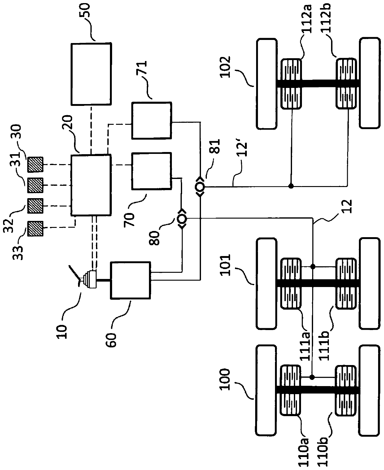
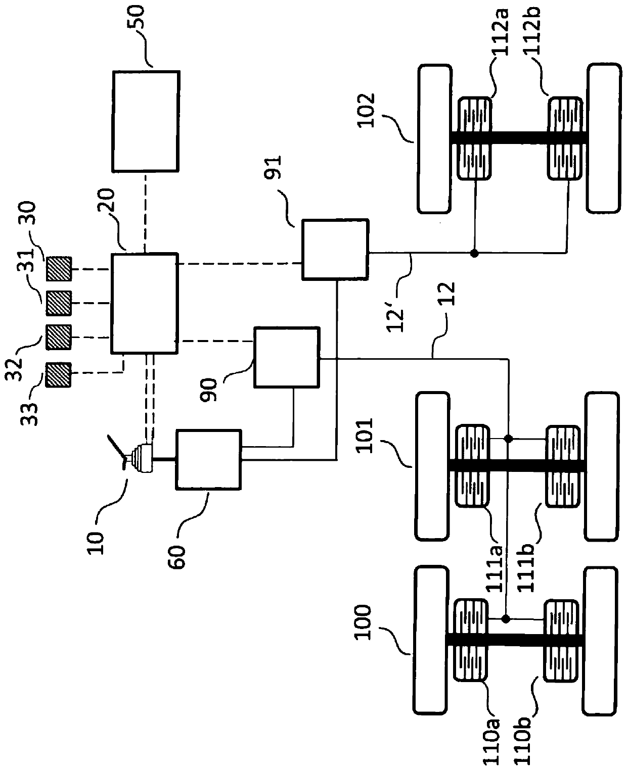
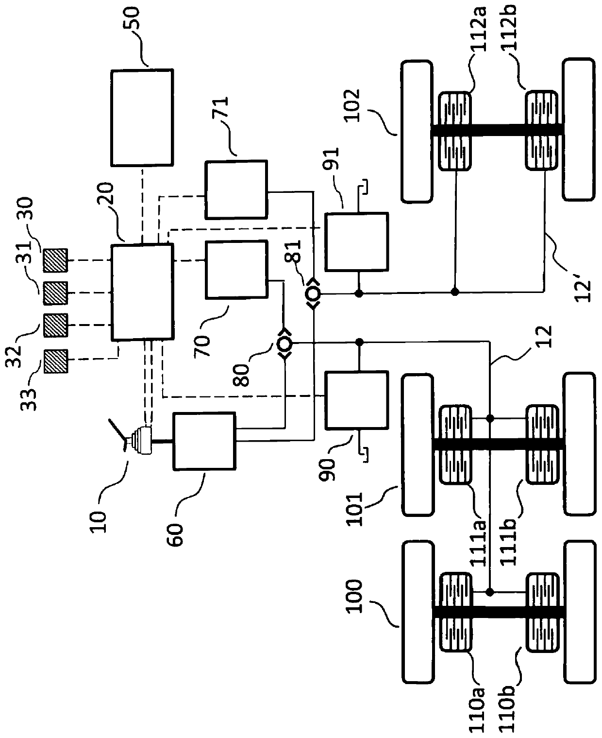
[0030] figure 1 A first embodiment of a braking device for a work machine according to the invention is schematically shown in . The work machine may be an excavator, a dump truck or dump truck, a wheel loader, a flatbed truck, or another type of construction machine. The braking system comprises a plurality of brakes 110a-b, 111a-b, 112a-b arranged on different axles 100, 101, 102 of the work machine, And said plurality of brakes 110a-b, 111a-b, 112a-b is used to brake the respective axle 100, 101, 102 or the differential of the respective axle 100, 101, 102. The brakes 110a-b, 111a-b, 112a-b are actuated via two hydraulic brake circuits 12, 12', wherein brake circuit 12 is associated with brakes 110a-b and 111a-b, and brake circuit 12' is associated with The brakes 112a-b are associated. In this example, axles 100 and 101 may be rear axles, and axle 102 may be a front axle of an articulated steer dump truck.

[0031]The braking arrangement comprises a brake pedal 10 whic...


PUM


Abstract

The invention relates to a braking device for a work machine comprising a pressure supply, a brake circuit, at least one brake actuable via the brake circuit, a manually controllable brake valve by means of which the brake circuit is actuable, a control unit, and at least one control valve that is controllable by the control unit and by means of which the brake circuit is actuable. In accordance with the invention, the total brake torque exerted by the at least one brake is adjustable by means of a corresponding control or regulation of the at least one control valve in dependence on at leasttwo input signals detectable by the control unit, with a first input signal relating to a current state of the manual actuation of the brake valve and a second input signal relating to a current driving state of the work machine.

Description

technical field [0001] The invention relates to a braking system for a work machine. Background technique [0002] Braking devices are known in vehicles and mobile work machines. These are usually control or regulation systems that can be manually controlled by the operator of the work machine. For this purpose, corresponding brake pedals or other actuating devices are usually arranged in the driver's compartment, and the braking process can be manually activated and controlled by means of them. [0003] A large number of work machines are equipped with braking devices (eg dual circuit braking systems) in which the brake circuit actuating the service brakes can be controlled manually via a brake valve, usually via a brake pedal coupled to the brake valve. Typically, the brake pressure of the manually actuatable brake valve is predefined for the characteristics of the brake pedal angle and is not adjustable. [0004] The disadvantage of this solution is that the difference...

Claims


Application Information

Patent Timeline
IPC IPC(8): B60T13/66
CPCB60T13/66B60T13/662B60T7/042B60T8/17B60T8/1701B60T8/18B60T8/246B60T8/326B60T13/586B60T13/686B60T2220/04B60T2250/04B60T2270/82
Inventor B·梅庭格尔M·史洛普M·穆克尔A·普尔
Owner LEIBHERR HYDRAULIKBAGGER GMBH
Learn More