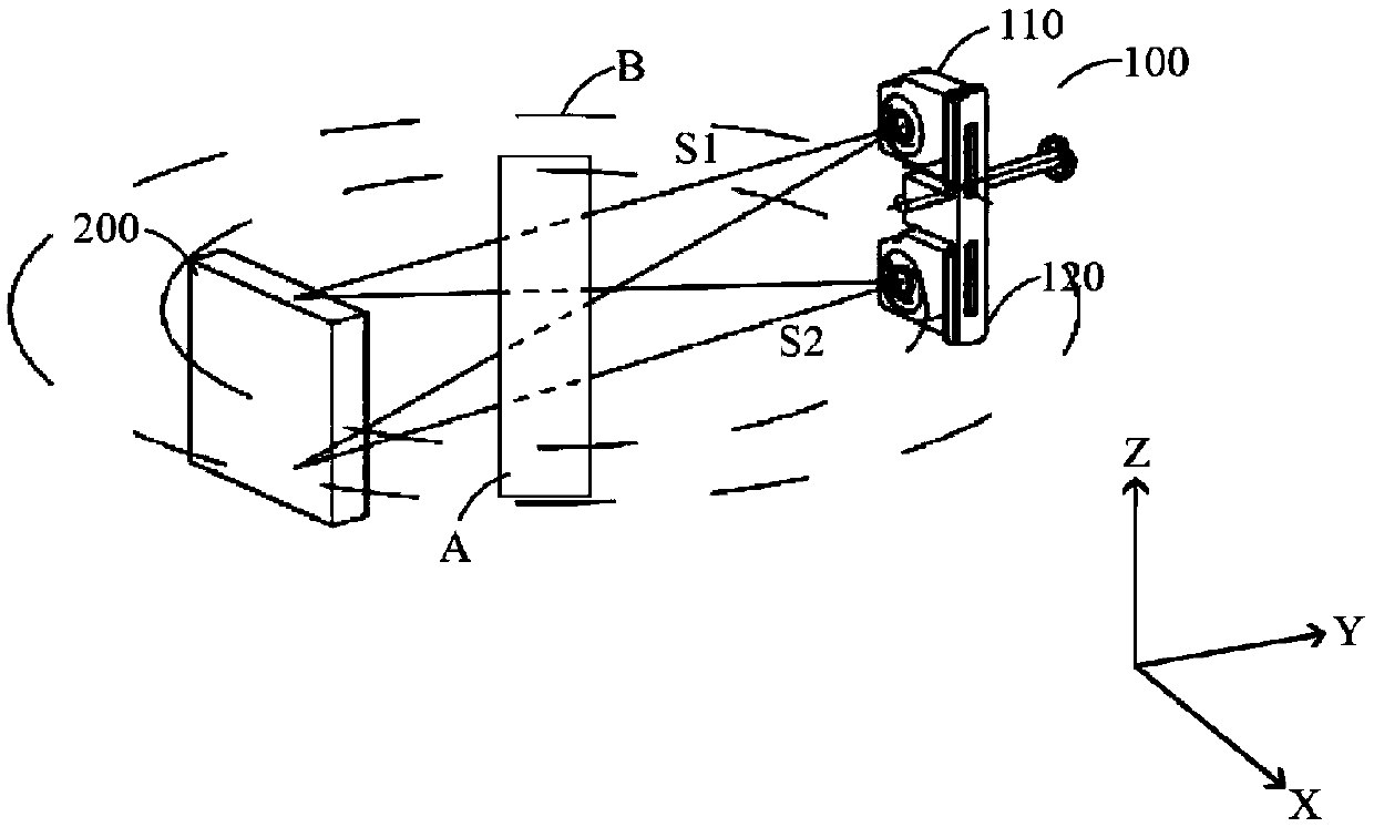
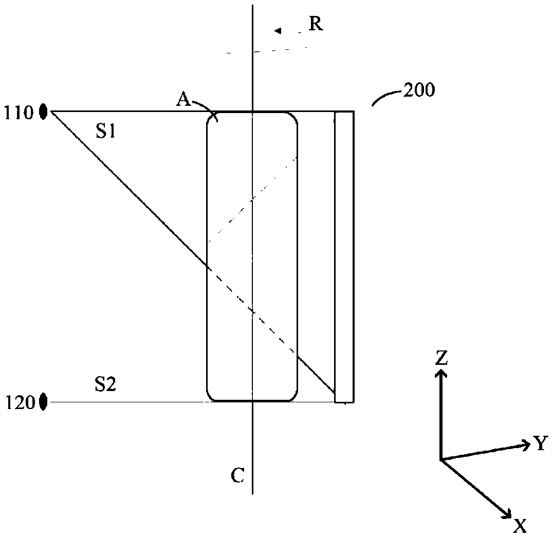
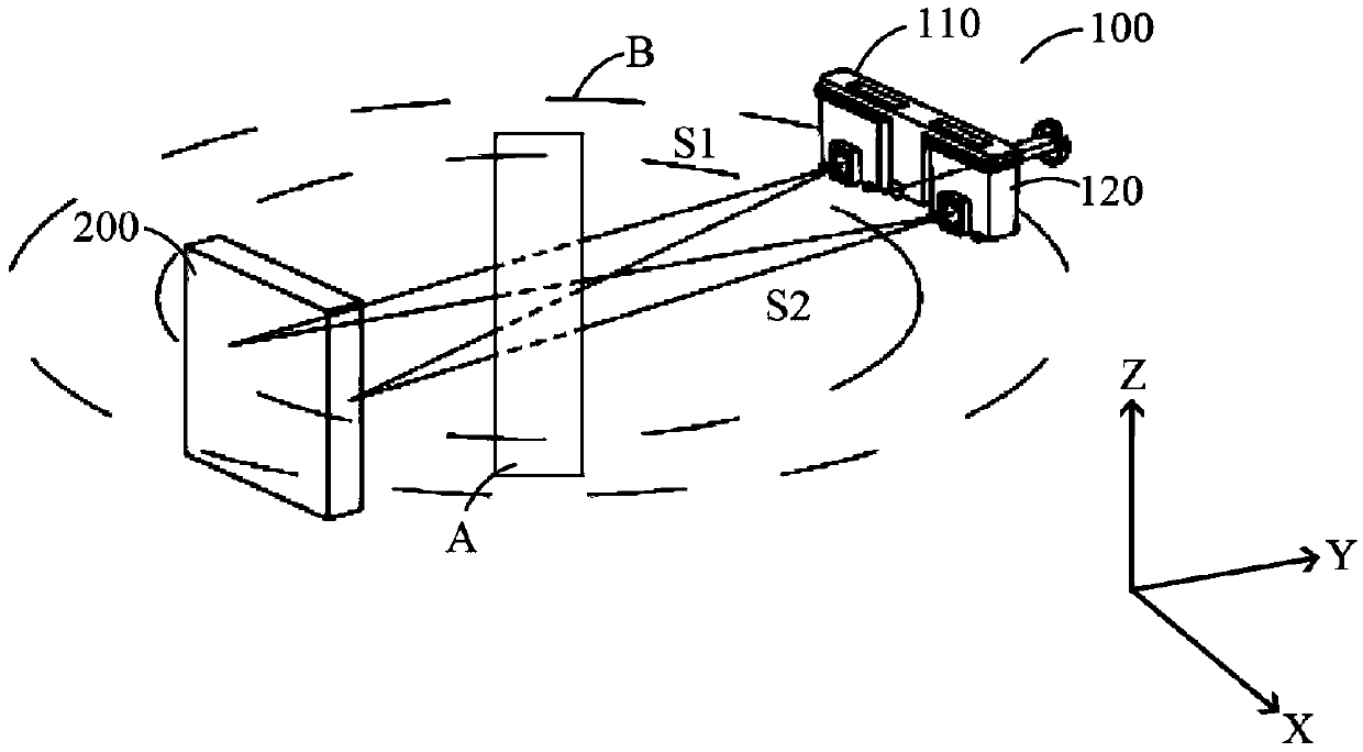
Oral cavity CT equipment

An oral and X-ray technology, applied in the field of oral CT, can solve the problems of expensive detectors, inability to obtain scanning images of the area of ​​interest, and inability to completely cover the light

Pending Publication Date: 2020-07-24
YOFO MEDICAL TECH CO LTD
View PDF0 Cites 0 Cited by
  • Summary
  • Abstract
  • Description
  • Claims
  • Application Information

AI Technical Summary

Problems solved by technology

Typically, oral CT is provided with an X-ray source and a detector that emits a cone-shaped beam. Due to the limited size of the detector (larger detectors are very expensive), the range of light that can be received by the detector is limited
In this way, when the projection body is large, the light received by the detector cannot completely cover the part of the projection body that needs to be scanned (hereinafter referred to as the region of interest), so that the entire scanning image of the region of interest cannot be obtained
[0003] As we all know, larger detectors are more expensive, so there is a need in the field to use smaller detectors to obtain larger projection volume images
[0004] In addition, the radiation sources of oral CT machines currently on the market are basically fixed, so the functions of the machines are limited by the fixed radiation sources
Such a CT machine can only be used in a single shooting mode, and cannot realize multi-functional complex shooting modes

Method used


Image

  • Oral cavity CT equipment
  • Oral cavity CT equipment
  • Oral cavity CT equipment

Examples


Embodiment Construction

[0051] The present application will now be described more fully hereinafter with reference to the accompanying drawings that illustrate various embodiments. This application may, however, be embodied in many different forms and should not be construed as limited to the embodiments set forth herein. Rather, these embodiments are provided so that this disclosure will be thorough and complete, and will fully convey the scope of the application to those skilled in the art. Like reference numerals refer to like elements throughout the specification and throughout the drawings.

[0052] It will be understood that when an element is referred to as being "on" another element, it can be directly on the other element or intervening elements may be present therebetween. In contrast, when an element is referred to as being directly on another element, there are no intervening elements present.

[0053] It will be understood that although the terms "first", "second", "third", etc. may be...


PUM


Abstract

The application discloses oral cavity CT equipment. The oral cavity CT equipment comprises an X-ray source configured to emit X-rays to irradiate a projection body, a detector configured to detect theX-rays passing through the projection body to generate data of the X-rays, and a rotation mechanism configured to make the X-ray source and the detector rotate about a rotation shaft about the projection body, wherein the X-ray source includes a plurality of X-ray source units, and the plurality of X-ray source units can rotate about the rotation shaft perpendicular to the surface of the detector. By means of the oral cavity CT equipment, multi-mode integration can be achieved, and the use performance of the oral cavity CT equipment is expanded.

Description

technical field [0001] This application relates to the field of oral CT. Background technique [0002] Imaging technologies, including, for example, X-ray imaging, CT (Computed Tomography, computer tomography), etc., have been widely used in many fields since their advent, especially in the field of medical inspection. Oral CT can reflect the tissue situation from a three-dimensional perspective, and can find subtle lesions that cannot be found in the projection angle of oral X-ray films. Generally, oral CT is provided with an X-ray source and a detector capable of emitting a cone-shaped beam. Since the size of the detector is limited (larger detectors are very expensive), the range of light received by the detector is limited. In this way, when the projected body is large, the light received by the detector cannot completely cover the part of the projected body that needs to be scanned (hereinafter referred to as the ROI), so that the entire scanned image of the ROI cannot...

Claims


Application Information

Patent Timeline
IPC IPC(8): A61B6/14A61B6/03
CPCA61B6/032A61B6/40A61B6/512
Inventor 王飞郭晓军徐燃
Owner YOFO MEDICAL TECH CO LTD
Why Eureka
Try Eureka