Cartilage endplate cutter and use method thereof

A technology of resectator and cartilage, which is applied in the field of medical device research, can solve the problems of prolonged anesthesia time for patients, unfavorable fast recovery for patients, and prolonged operation time, so as to increase surgical safety, facilitate rapid recovery, and reduce surgical costs.

Pending Publication Date: 2020-07-24
WEST CHINA HOSPITAL SICHUAN UNIV
View PDF0 Cites 2 Cited by
  • Summary
  • Abstract
  • Description
  • Claims
  • Application Information

AI Technical Summary

Problems solved by technology

[0004] The first method uses a curette to slowly scrape off the cartilage endplate, which takes a lot of time and is not easy to scrape off. The whole operation will take a long time to scrape off the cartilage endplate, resulting in prolonged anesthesia time for the patient. Increased costs, and not conducive to the rapid recovery of patients
[0005] The second type uses nucleus pulposus forceps to bite. When using nucleus pulposus forceps to bite, the cartilage endplate will be filamentous. The nucleus pulposus forceps has no cutting effect and cannot cut off the filamentous cartilage endplate. The flocculent cartilage endplate cannot be scraped off; the head of the nucleus pulposus forceps is too thick, and the degree of opening after entering the intervertebral space is limited, and only a little cartilage endplate can be bitten each time, which prolongs the operation time and prolongs the patient's anesthesia time , the cost increases, and it is not conducive to the rapid recovery of patients
[0006] The third method uses curettes and nucleus pulposus forceps in combination, but there is still the problem that the above-mentioned operation time is too long, resulting in prolonged anesthesia time and increased costs for patients, which is not conducive to the rapid recovery of patients

Method used


Image

  • Cartilage endplate cutter and use method thereof
  • Cartilage endplate cutter and use method thereof
  • Cartilage endplate cutter and use method thereof

Examples


Embodiment Construction

[0027] In order to make the object, technical solution and advantages of the present invention clearer, the present invention will be further described in detail below in conjunction with the accompanying drawings.

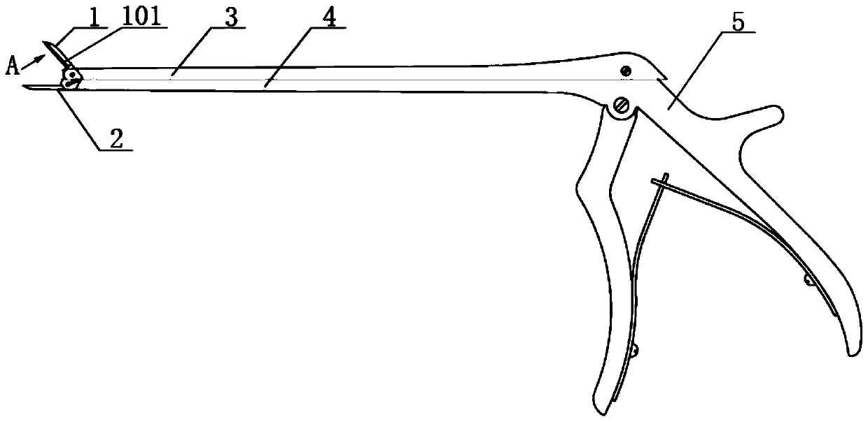
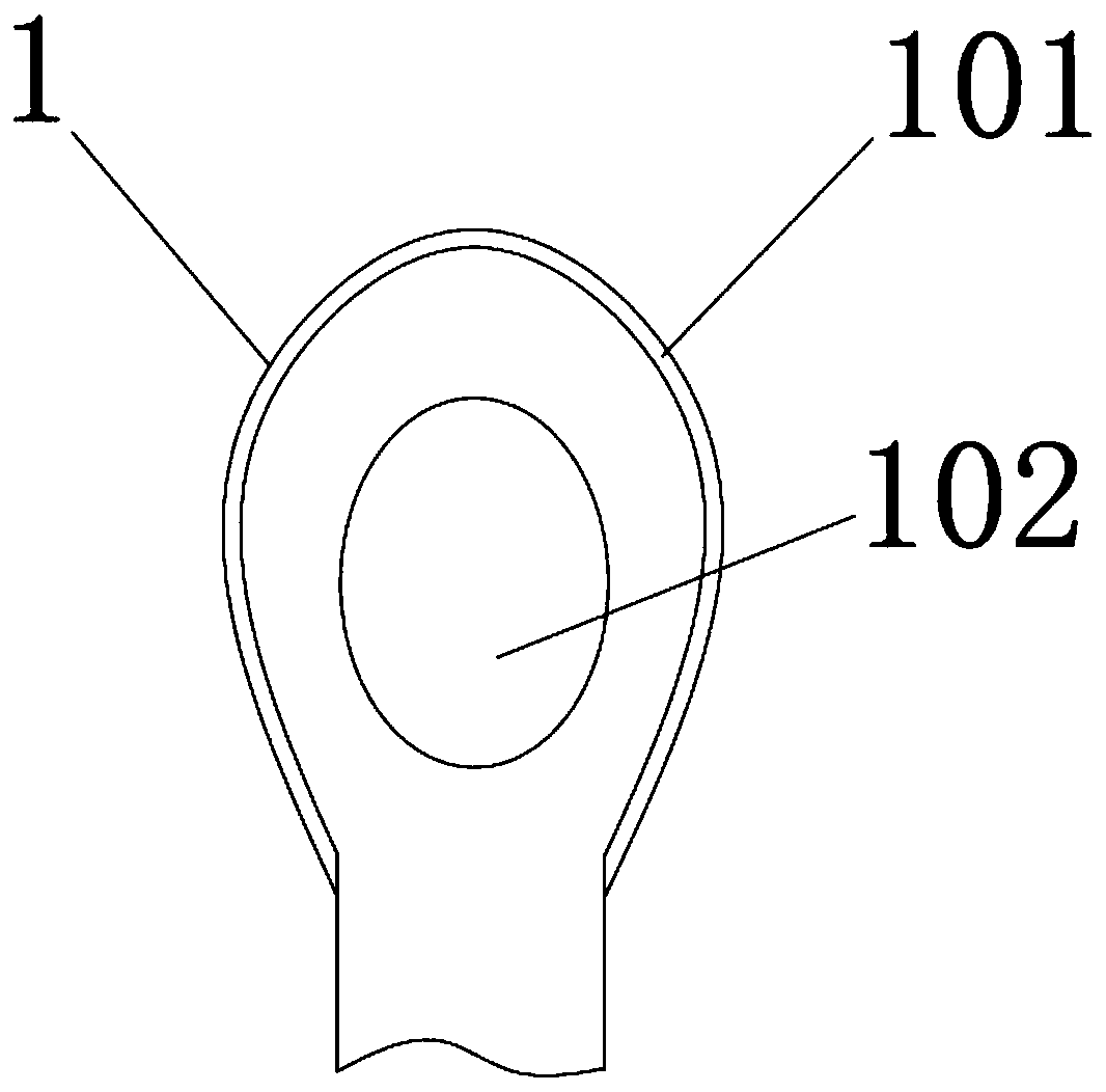
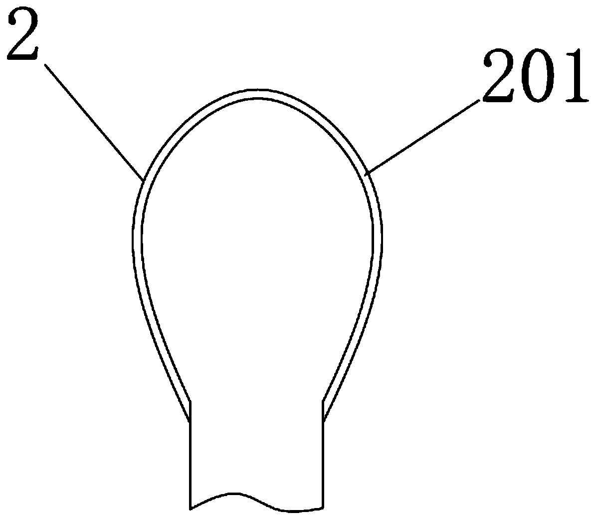
[0028] A cartilage endplate resector of the present invention comprises: upper head 1, lower head 2, movable arm 3, fixed arm 4, handle 5; lower head 2 is fixedly connected with the front end of fixed arm 4, upper head 2 is movably connected with the front pin shaft of the movable arm 3, and the tail of the upper head 1 is connected with the spring wire in the movable arm 3, and the spring wire is connected with the handle 5; the movable arm 3 and the fixed arm 4 are all connected with the handle 5 ) connection; the middle part of the upper head 1 is provided with a through hole 102; the edge of the upper head 1 is provided with a micro blade 101.

[0029] Preferably, the edge of the lower head 2 is provided with a groove 201 , and the groove 201 is adapted to the...


PUM


Abstract

The invention discloses a cartilage endplate cutter and a use method thereof. The cutter comprises an upper head, a lower head, a movable arm, a fixed arm and a handle, wherein the lower head is fixedly connected with the front end of the fixed arm, the upper head is movably connected with a front end pin shaft of the movable arm, the tail of the upper head is connected with a spring wire in the movable arm, and the spring wire is connected with a handle; the movable arm and the fixed arm are connected with the handle; a through hole is formed in the middle of the upper head; and a micro bladeis arranged on the edge of the upper head. The use method comprises the following steps: the handle is held, the lower head is shoved into an interbody gap, a cartilage endplate is pried and stripped, the handle is tightly held to control the upper head, the micro blade of the upper head is meshed with a groove of the lower head, the cartilage endplate is cut off, and the cut-off cartilage endplate is clamped in the through hole of the upper head and finally taken out. The cutter can rapidly separate the cartilage endplate from a bony endplate, shortens the operation time, is convenient to operate in a narrow interbody gap space, reduces the operation cost and facilitates rapid recovery of a patient.

Description

technical field [0001] The invention relates to the field of medical device research, in particular to a cartilage endplate resecting device and a method for using the same. Background technique [0002] In intervertebral disc surgery, it is necessary to remove all the intervertebral disc, nucleus pulposus tissue, annulus fibrosus, and then the endplate on the surface of the vertebral body. The cartilage endplate is dense and fits closely with the bony endplate; the cartilage endplate has toughness and is not easily broken during scraping, and the cartilage endplate is flocculent during scraping, which is not easy to scrape clean, and the whole process is time-consuming and laborious . [0003] There are three methods for the existing clinical curettage of the cartilage endplate. [0004] The first method uses a curette to slowly scrape off the cartilage endplate, which takes a lot of time and is not easy to scrape off. The whole operation will take a long time to scrape o...

Claims


Application Information

Patent Timeline
Patent Type & Authority Applications(China)
IPC IPC(8): A61B17/16
CPCA61B17/1659A61B17/1671
Inventor 马立泰杨毅刘浩
Owner WEST CHINA HOSPITAL SICHUAN UNIV
Why Eureka
Try Eureka