

Automatic pushing device for toilet paper cutting
A technology for pushing device and toilet paper, applied in metal processing and other directions, can solve the problems of inability to ensure production safety, uncontrollable length of toilet paper, and inability to meet production needs, etc., and achieves the effect of simple and convenient use of the device and improved work efficiency.
- Summary
- Abstract
- Description
- Claims
- Application Information
AI Technical Summary
Problems solved by technology
Method used
Image

Examples
Embodiment 1
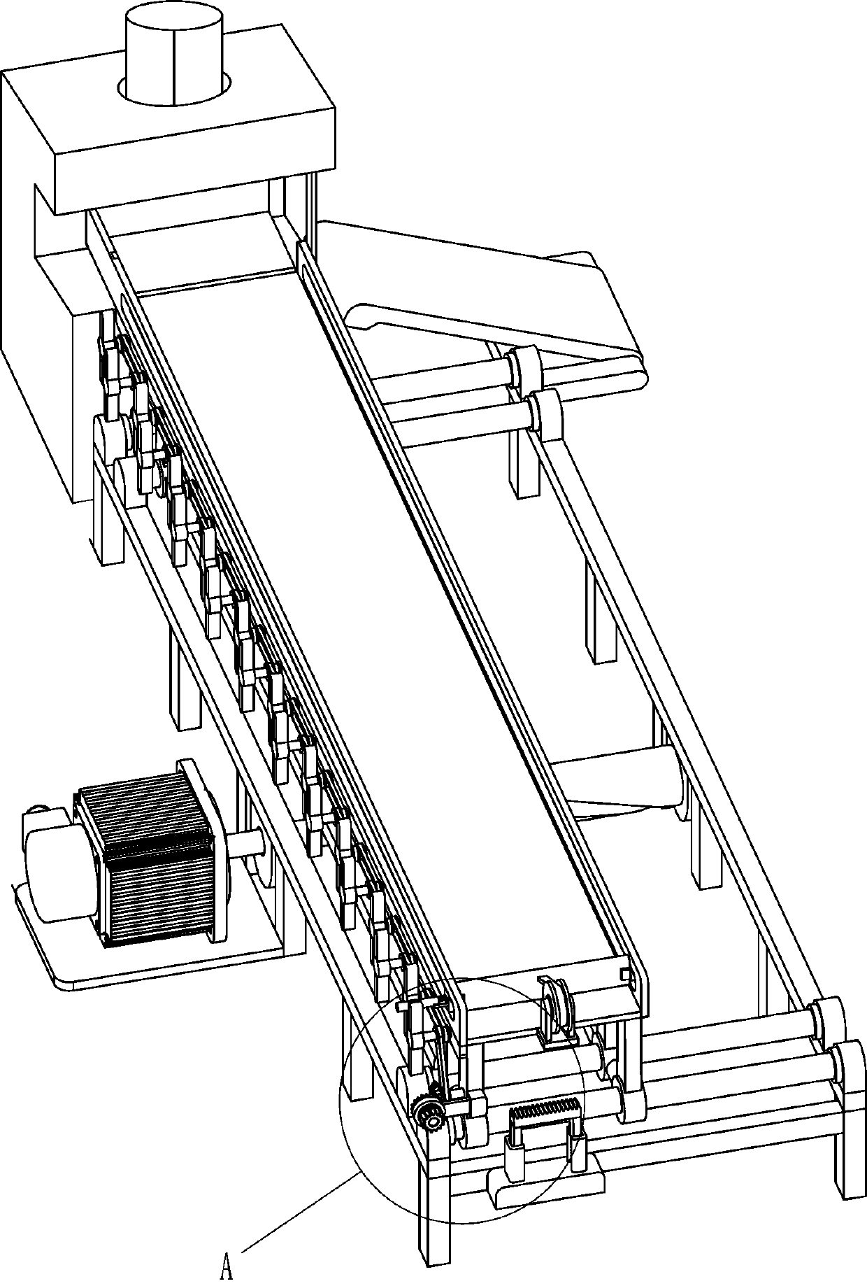
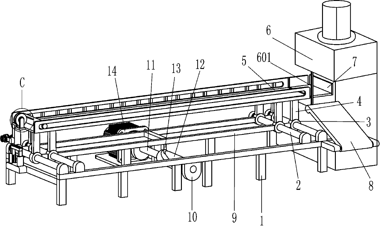
[0028] An automatic pusher for toilet paper cutting, such as Figure 1-5 As shown, it includes a frame 1, a sliding rod 2, a sliding sleeve 3, a support plate 4, a placement plate 5, a cutting mechanism, a connecting plate 9, a driving mechanism and a transmission mechanism, and the left and right sides of the frame 1 are fixedly equipped with sliding rods. 2. The number of sliding rods 2 is at least 4. The sliding sleeve 3 is slidably installed on the rear side of the sliding rod 2 and the middle position of the sliding rod 2. The upper end of the sliding sleeve 3 is fixedly installed with the support plate 4, and the upper end of the support plate 4 is fixedly installed with The board 5 is placed, the cutting mechanism is installed on the right side of the frame 1, the connecting plate 9 is fixedly connected to the sliding sleeve 3, the driving mechanism is installed on the rear side of the center of the frame 1, and the driving mechanism cooperates with the connecting plate ...
Embodiment 2
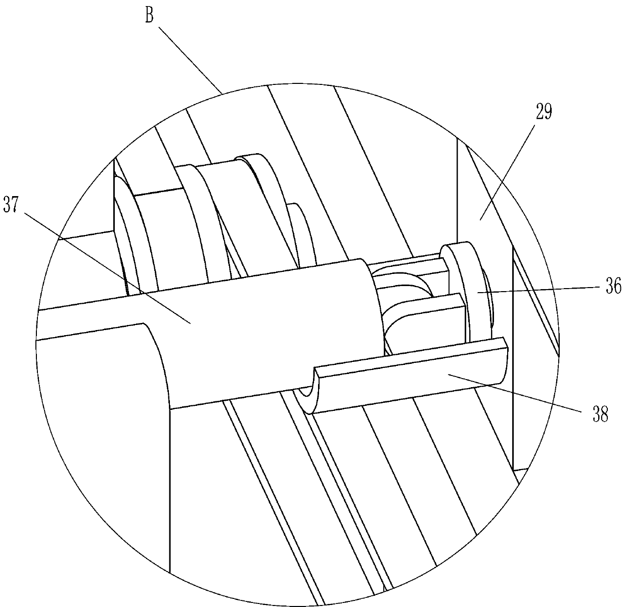
[0037] On the basis of Embodiment 1, refer to figure 1 , figure 2 with Figure 5 Shown, also include square block 39, the second mounting plate 40, reel 41, torsion spring 42 and stay cord 43, place plate 5 left middle positions are fixedly installed with square block 39, square block 39 tops Both front and rear sides are fixedly equipped with a second mounting plate 40, and a reel 41 and a torsion spring 42 are rotatably installed between the two second mounting plates 40. The torsion spring 42 is located at the center of the inner side of the reel 41, and the reel 41 is wound with a stay cord 43 , and the stay cord 43 is connected to the horizontal plate 30 .
[0038] When the transmission mechanism drives the horizontal plate 30 to move to the right, the stay cord 43 is also stretched to the right, so that the reel 41 is rotated to release the stay cord 43, and the torsion spring 42 inside the reel 41 is pulled. Due to the setting of the single bearing 16, the push plat...
PUM
 Abstract
Description
Claims
Application Information