
Drive circuit and driving method of display array

A display array and drive circuit technology, applied in the direction of static indicators, instruments, etc., can solve the problems of low scanning efficiency and inability to realize high-resolution display drive, and meet the display requirements of resolution, save lighting time, and high-resolution The effect of the rate of display demand

Active Publication Date: 2020-07-24
INST OF MICROELECTRONICS CHINESE ACAD OF SCI
View PDF5 Cites 4 Cited by
  • Summary
  • Abstract
  • Description
  • Claims
  • Application Information

AI Technical Summary

Problems solved by technology

However, the method of controlling light emission at different time periods will result in low scanning efficiency and cannot realize high-resolution display driving.

Method used


Image

  • Drive circuit and driving method of display array
  • Drive circuit and driving method of display array
  • Drive circuit and driving method of display array

Examples


Embodiment Construction

[0023] Hereinafter, embodiments of the present disclosure will be described with reference to the drawings. It should be understood, however, that these descriptions are exemplary only, and are not intended to limit the scope of the present disclosure. Also, in the following description, descriptions of well-known structures and techniques are omitted to avoid unnecessarily obscuring the concept of the present disclosure.

[0024] Various structural schematic diagrams according to embodiments of the present disclosure are shown in the accompanying drawings. The figures are not drawn to scale, with certain details exaggerated and possibly omitted for clarity of presentation. The shapes of the various regions and layers shown in the figure, as well as their relative sizes and positional relationships are only exemplary, and may deviate due to manufacturing tolerances or technical limitations in practice, and those skilled in the art will Regions / layers with different shapes, s...


PUM


Abstract

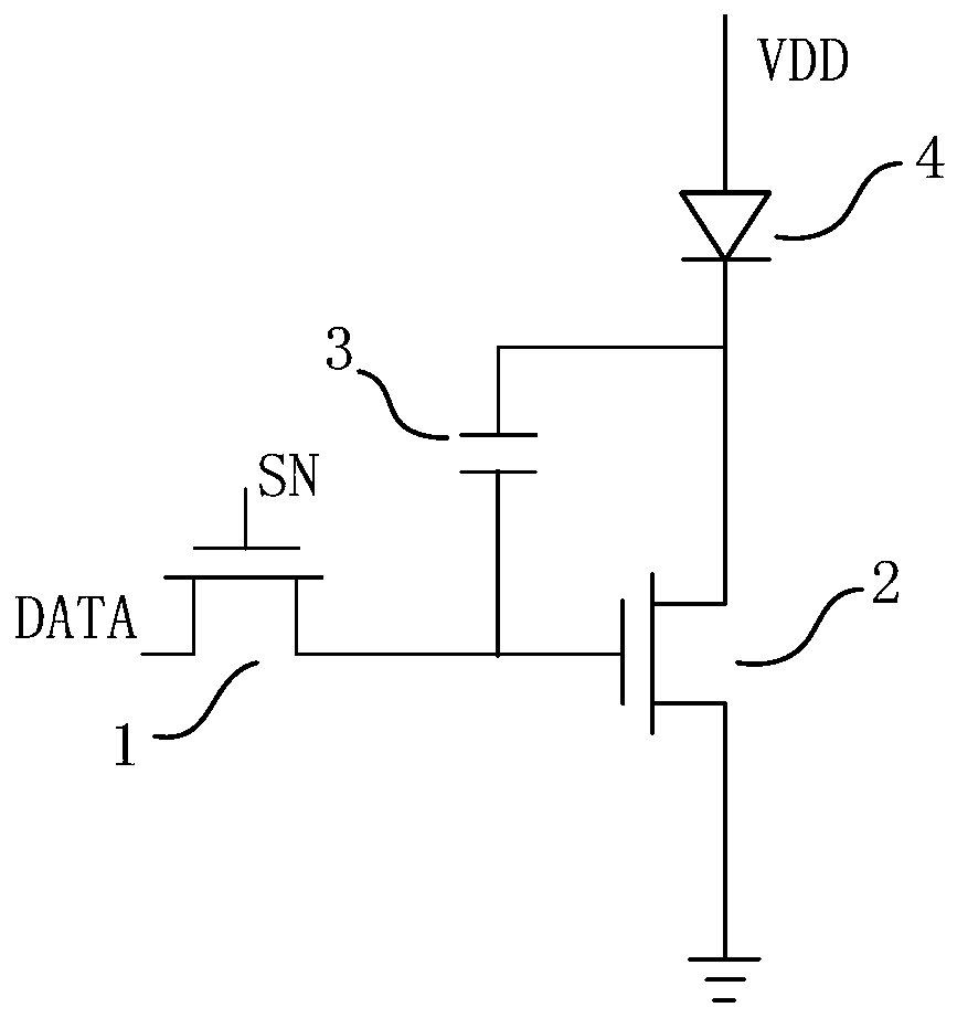
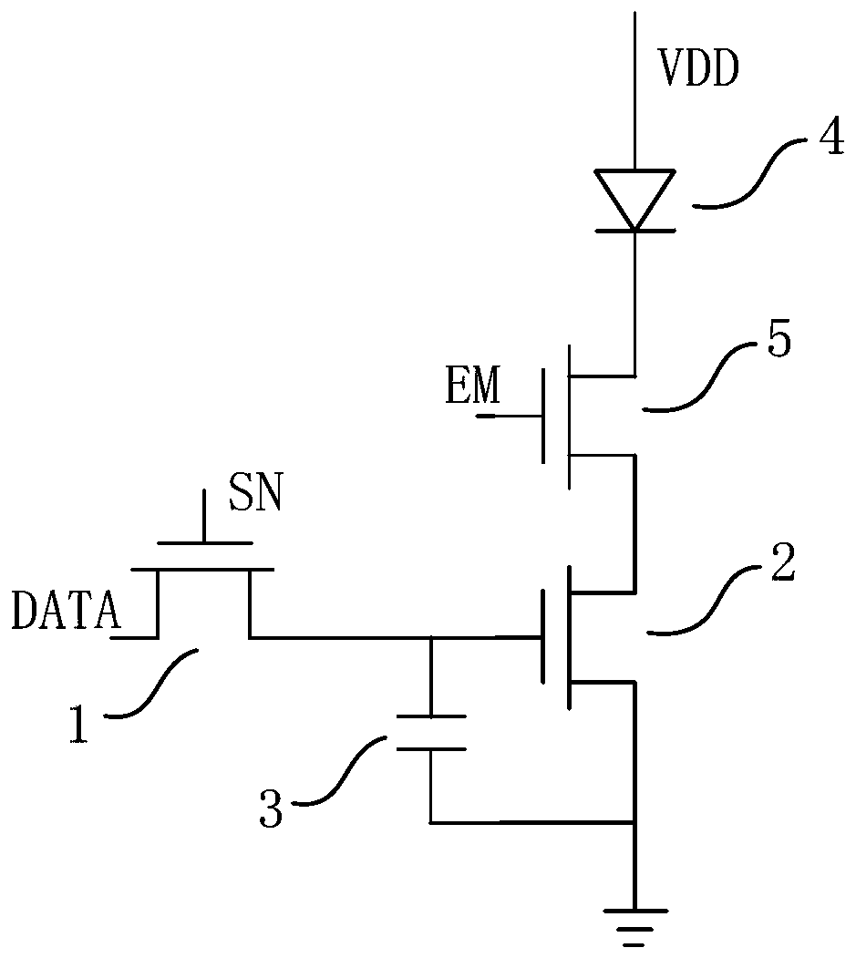
The invention discloses a drive circuit and a driving method of a display array, relates to the technical field of display, and aims to meet high-resolution display requirements. The drive circuit ofthe display array comprises m rows * n columns of pixel driving units. Each pixel driving unit comprises a plurality of gray scale control periods in one driving period. The pixel driving unit comprises a gating transistor, a first driving transistor, a storage capacitor and a light emitting circuit, wherein the gating transistor is electrically connected with the control end of the first drivingtransistor and the storage capacitor respectively. And each gating transistor is used for writing m data signals into each storage capacitor in a one-to-one correspondence manner under the control ofm rows of scanning signals in each gray scale control time period. A first electrode of the first driving transistor is electrically connected with the light emitting circuit. The second electrode ofthe first driving transistor is grounded. And each first driving transistor is used for controlling each light emitting circuit to work under the control of m data signals in each gray scale control period.

Description

technical field [0001] The invention relates to the field of display technology, in particular to a driving circuit and a driving method of a display array. Background technique [0002] The driving circuit of the existing display array adopts the method of controlling the light emission of pixels in each row at different periods after the scanning and gating stage, so as to realize the control of the pixel array. However, the way of controlling light emission at different time periods will result in low scanning efficiency and cannot realize high-resolution display driving. Contents of the invention [0003] The purpose of the present invention is to provide a driving circuit and a driving method of a display array, which adopts a driving method in which the light-emitting circuits of each row emit light at the same time, so as to meet the display requirement of high resolution. [0004] In order to achieve the above object, the present invention provides a driving circu...

Claims


Application Information

Patent Timeline
Patent Type & Authority Applications(China)
IPC IPC(8): G09G3/32G09G3/3208G09G3/3266
CPCG09G3/32G09G3/3208G09G3/3266
Inventor 耿玓苏悦李泠卢年端刘明
Owner INST OF MICROELECTRONICS CHINESE ACAD OF SCI
Learn More