Power transmission line robot capable of automatically adjusting postures and automatic posture adjusting method

A transmission line, automatic adjustment technology, applied in the direction of overhead lines/cable equipment, etc., can solve the problems that affect the working angle and walking safety of the whole machine, affect the battery life of the whole machine, portability, large volume and weight, etc.

Pending Publication Date: 2020-07-24
STATE GRID ZHEJIANG ELECTRIC POWER CO LTD JINHUA POWER SUPPLY CO +2
View PDF0 Cites 7 Cited by
  • Summary
  • Abstract
  • Description
  • Claims
  • Application Information

AI Technical Summary

Problems solved by technology

In extreme cases, the position of the center of gravity may shift to a position that cannot maintain the balance of the robot, affecting the working angle and walking safety of the whole machine
The built-in gyrosc...

Method used


Image

  • Power transmission line robot capable of automatically adjusting postures and automatic posture adjusting method
  • Power transmission line robot capable of automatically adjusting postures and automatic posture adjusting method
  • Power transmission line robot capable of automatically adjusting postures and automatic posture adjusting method

Examples


Embodiment 1

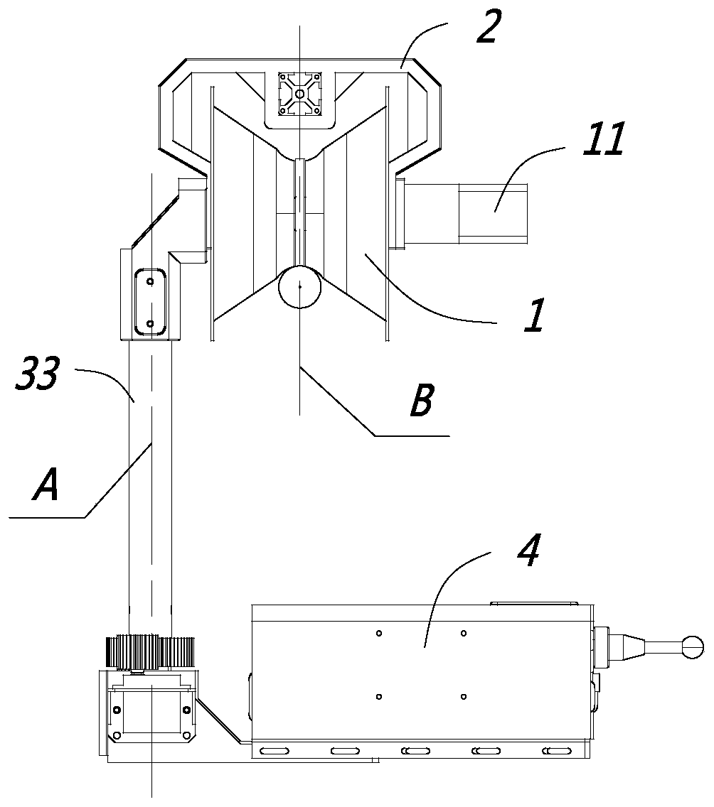
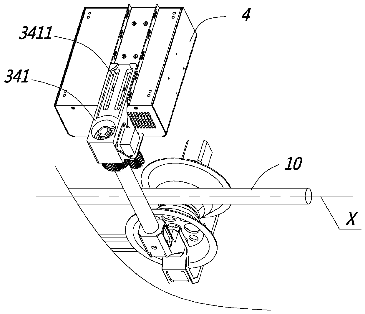
[0034] like Figure 1 to Figure 3 As shown, this embodiment is a power transmission line robot with automatic posture adjustment, including an electric control box 4 and two walking wheels 1, the walking wheels 1 are usually V-shaped wheels, and the walking wheels 1 are used to hang on the power transmission line 10, the travel wheel 1 is connected with a travel motor 11, and the travel motor 11 drives the travel wheel 1 to rotate, thereby driving the entire transmission line robot to walk on the transmission line 10, and each travel wheel 1 is provided with a travel wheel bracket 2 The road wheel 1 is rotatably mounted on the road wheel bracket 2, at least one of the two road wheel brackets 2 is equipped with an angle sensor, and at least one of the two road wheel brackets 2 is provided with a rotation mechanism below, The line connecting the two road wheels 1 is the walking axis X, the rotating mechanism includes a rotating central axis Y, the rotating central axis Y is perp...

Embodiment 2

[0053] The difference between this embodiment and Embodiment 1 is that the angle sensor in this embodiment only detects the horizontal angle in the lateral direction, because the balance degree in the lateral direction has a greater impact on the transmission line robot, and the balance degree in the longitudinal direction has a greater impact on the power transmission line. Line robots have relatively little impact.

[0054] In this embodiment, the first rotating mechanism and the second rotating mechanism rotate in opposite directions at the same time.

[0055] In this embodiment, there may be only one angle sensor, and of course there may be two angle sensors, but both of these two angle sensors are used to detect the lateral horizontal angle.


PUM


Abstract

The invention discloses a power transmission line robot capable of automatically adjusting postures, which belongs to the field of power maintenance auxiliary tools. The power transmission line robotcomprises an electric cabinet and two walking wheels; each walking wheel is provided with a walking wheel support; at least one of the walking wheel supports is provided with an angle sensor; a rotating mechanism is arranged below at least one of the walking wheel supports; the connecting line between the two walking wheels is a walking axis; the rotating central axis of the rotating mechanism isperpendicular to the walking axis and located on the transverse side of a power transmission line; the electric control box is connected with the rotating mechanism; the rotating mechanism comprises arotating motor; and the rotating motor drives the gravity center of the electric control box to be close to or away from the power transmission line in the horizontal direction. The invention furtherdiscloses an automatic posture adjusting method of the power transmission line robot. The method has the advantages that the balance of the power transmission line robot can be monitored and adjustedin real time to ensure the posture stability of the power transmission line robot.

Description

【Technical field】 [0001] The invention relates to a transmission line robot with automatic posture adjustment and a method for automatic posture adjustment, belonging to the field of electric power maintenance auxiliary tools. 【Background technique】 [0002] Transmission line robots are a type of special robots that replace manual work on high-voltage wires and ground wires. During the operation, they need to maintain a balanced posture to avoid the difficulty in aligning the working head and off-line deviation caused by tilting. In the prior art, the balance of the center of gravity is mainly maintained by adopting static adjustment equipment, that is, the center of gravity of the equipment is fixed, and the equipment can only maintain balance when it is in a standby state. The center of gravity of the transmission line robot will change in real time during the process of walking over obstacles and working, which will affect the posture. Therefore, there is a need for a de...

Claims


Application Information

Patent Timeline
IPC IPC(8): H02G1/02
CPCH02G1/02
Inventor 方玉群姜文东赵寿生王斌秦威南梁加凯张帆朱凯刘凯彭勇沈彦南
Owner STATE GRID ZHEJIANG ELECTRIC POWER CO LTD JINHUA POWER SUPPLY CO
Why Eureka
Try Eureka