
Drainage and puncture device for department of cardiology

A technique of cardiology and puncture tube, applied in the field of drainage and puncture devices for cardiology, can solve the problems of increasing the difficulty of treatment for doctors, increasing the operation procedure, prolonging the operation time, etc., to reduce the difficulty of treatment, simple and convenient operation, and adjust the depth of puncture/drainage. Effect

Inactive Publication Date: 2020-07-28
孔令刚
View PDF9 Cites 0 Cited by
  • Summary
  • Abstract
  • Description
  • Claims
  • Application Information

AI Technical Summary

Problems solved by technology

[0002] With the continuous development of society, the continuous progress of science, the continuous improvement of medicine, and the continuous innovation of various medical devices, the drainage / puncture device for cardiology is an indispensable medical device in the hospital's cardiology operation. Therefore, it is currently on the market There are many types of such devices, which can basically meet people's needs, but there are still some problems. The traditional cardiology drainage / puncture device is not equipped with a device that can adjust the insertion depth of the drainage head / puncture needle. Doctors When inserting the drainage head / puncture needle, the required depth cannot be selected simply and easily, which brings inconvenience to the operation, increases the difficulty of the doctor's treatment, and prolongs the operation time. The clot-like dirt in the effusion is additionally separated and extracted for easy testing, which increases the operating procedures

Method used


Image

  • Drainage and puncture device for department of cardiology
  • Drainage and puncture device for department of cardiology
  • Drainage and puncture device for department of cardiology

Examples


Embodiment

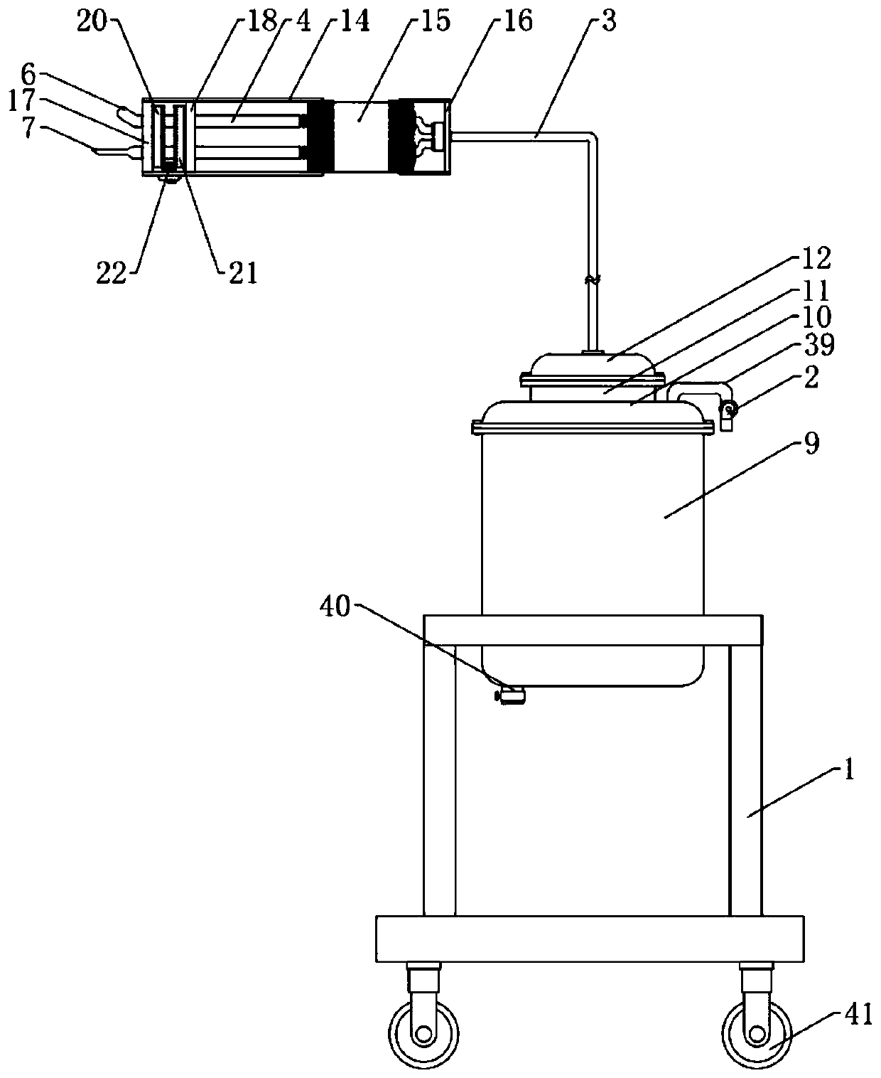
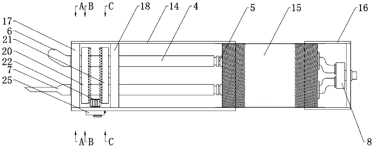
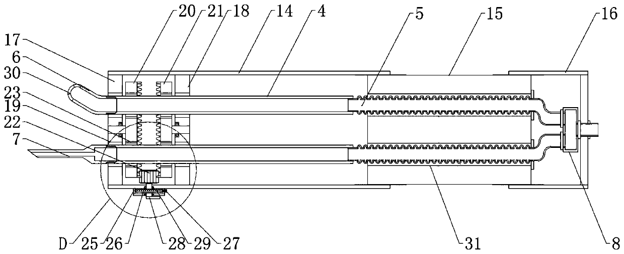
[0042] A drainage and puncture device for cardiology, comprising a support frame 1, a liquid collection tank arranged on the upper end of the support frame, a negative pressure pump 2 provided on the liquid collection tank for extracting negative pressure from the liquid collection tank, and a drainage tube 3. A drainage puncture body connected to the liquid collection tank; at least two drainage puncture tubes with telescopic functions are movably installed on the drainage puncture body, and a locking part for locking the position of the drainage puncture tube is also provided on the drainage puncture body, The drainage puncture tube is composed of interconnected hard tube 4 and soft corrugated tube 5, the end of the hard tube 4 of the drainage puncture tube is detachably installed with a drainage head 6 / puncture needle 7, and the drainage puncture tube The end of the flexible bellows 5 of the pipe is connected to the diversion pipe 3 through the conversion head 8; The extern...


PUM


Abstract

The invention relates to a drainage and puncture device for a department of cardiology. The drainage and puncture device comprises a support frame, a liquid collection tank, a negative pressure pump and a drainage and puncture body connected with the liquid collection tank through a flow guide pipe, wherein at least two drainage and puncture tubes with a telescopic function are movably arranged onthe drainage and puncture body; a locking component for locking the positions of the drainage and puncture tubes is also arranged on the drainage and puncture body; each drainage and puncture tube iscomposed of interconnected hard tube and soft corrugated tube; a drainage head / puncture needle is detachably arranged at the end part of the hard tube of each drainage and puncture tube; the end partof the soft corrugated tube of each drainage and puncture tube is connected with the flow guide pipe through an adapter; the liquid collection tank comprises a tank body, a tank cover, an external tank body and an external tank cover; a filter barrel is inserted and arranged in the tank body; and a drive component for driving the filter barrel to rotate is arranged in the external tank body. Thedrainage and puncture device can select drainage / puncture according to operation requirements, conveniently adjusts the puncture / drainage depth and contributes to reduction of the treatment difficultyof a doctor.

Description

technical field [0001] The invention belongs to the technical field of medical devices, in particular to a drainage and puncture device for cardiology. Background technique [0002] With the continuous development of society, the continuous progress of science, the continuous improvement of medicine, and the continuous innovation of various medical devices, the drainage / puncture device for cardiology is an indispensable medical device in the hospital's cardiology operation. Therefore, it is currently on the market There are many types of such devices, which can basically meet people's needs, but there are still some problems. The traditional cardiology drainage / puncture device is not equipped with a device that can adjust the insertion depth of the drainage head / puncture needle. Doctors When inserting the drainage head / puncture needle, the required depth cannot be selected simply and easily, which brings inconvenience to the operation, increases the difficulty of the doctor'...

Claims


Application Information

Patent Timeline
Patent Type & Authority Applications(China)
IPC IPC(8): A61B17/34
CPCA61B17/3415A61B17/3494
Inventor 不公告发明人
Owner 孔令刚
Learn More