Auxiliary stent placement device and application method thereof

A delivery device and accommodating space technology, applied in the field of stent auxiliary placement devices, can solve the problems of failure of the whole set of equipment, bending of the core tube, deformation of the outer tube, etc., so as to reduce the difficulty of installation, avoid bending or deformation, and ensure a straight line degree of effect

Pending Publication Date: 2020-07-28
CHANGZHOU HEALTH MIRCROPORT MEDICAL DEVICE
View PDF0 Cites 0 Cited by
  • Summary
  • Abstract
  • Description
  • Claims
  • Application Information

AI Technical Summary

Problems solved by technology

It is very difficult to shrink all of them into the outer tube of the stent delivery device, and it is very likely to cause the core tube of the stent delivery device to bend or the outer tube to deform. Any of the above defects will lead to the failure of the entire set of equipment. In addition, doctors wear gloves in the operating room Operation will make the above process more difficult

Method used


Image

  • Auxiliary stent placement device and application method thereof
  • Auxiliary stent placement device and application method thereof
  • Auxiliary stent placement device and application method thereof

Examples


Embodiment 1

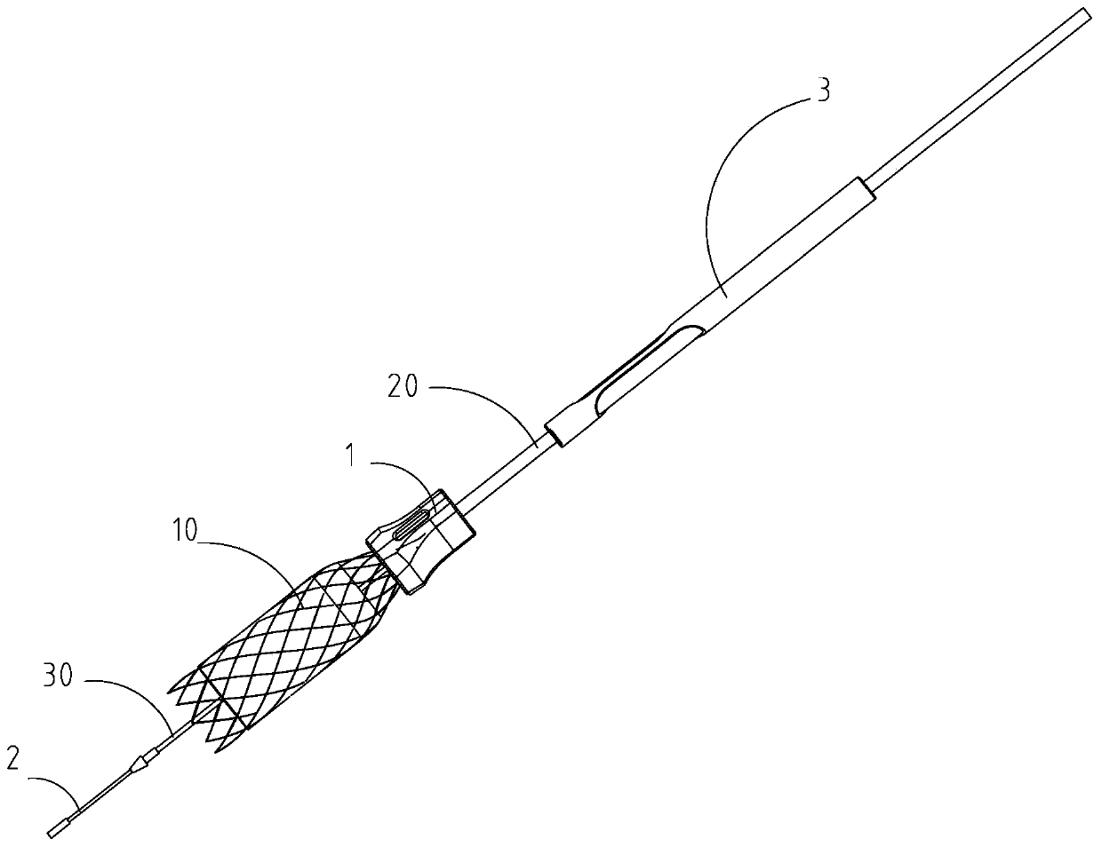
[0050] The stent delivery device is an existing technology, and the stent 10 of the stent delivery device needs to be placed between the outer tube 20 and the core tube 30 so that the stent 10 can be delivered by the stent delivery device.

[0051] In this embodiment, the proximal end of the stent delivery device refers to the end of the core tube 30 .

[0052] like Figure 1~6 As shown, a stent auxiliary placement device is used to place the stent 10 between the outer tube 20 and the core tube 30 of the stent delivery device, and it includes:

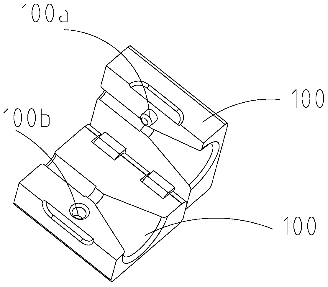
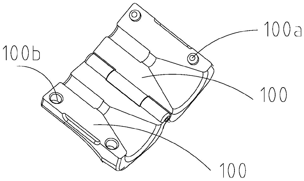
[0053] Connecting piece 1, said connecting piece 1 is suitable for being installed on the stent delivery device, said connecting piece 1 has a channel, at least part of said channel has The closing section 11 gradually closed in the end direction; wherein,

[0054] After the connecting piece 1 is mounted on the stent delivery device, the stent 10 is adapted to enter the accommodating space between the outer tube 20 and the core tube ...

Embodiment 2

[0089] A method of using the stent auxiliary placement device in Embodiment 1, the specific steps of the method include:

[0090] S0: Take out the connector 1, the auxiliary sleeve 3, the support rod 2, and the bracket 10 and place them on a clean table;

[0091] S1: Take out the stent delivery device, loosen the nut on the three-way valve of the stent delivery device, push the core tube 30 out of the stent delivery device, and insert the support rod 2 into the soft end of the core tube 30;

[0092] S11: Insert the auxiliary sleeve 3 from the core tube 30 into the outer tube 20 and advance to about 50 mm from the end surface of the outer tube 20;

[0093] S2: Pick up the opened connector 1, make the end surface of the outer tube 20 flush with the step surface on the connector 1, cover the connector 1, and make the channel communicate with the accommodation space between the outer tube 20 and the core tube 30 ;

[0094] S3: Pass the stent 10 through the core tube 30, insert t...


PUM


Abstract

The invention discloses an auxiliary stent placement device and an application method thereof. The auxiliary stent placement device is used for placing a stent between an outer tube and a core tube ofa stent conveyer. The auxiliary stent placement device comprises a connector, wherein the connector is suitable for being installed on the stent conveyer; the connector is provided with a channel; atleast one part of the channel is provided with a convergent section which is gradually closed in a direction from a proximal end to a distal end after the connector is arranged on the stent conveyer;and after the connector is arranged on the stent conveyer, the stent is suitable for entering an accommodating space between the outer tube and the core tube after passing through the convergent section. According to the auxiliary stent placement device, the stent can be rapidly installed in the stent conveyer, so that the phenomenon that the stent is pre-installed in the stent conveyer and cannot be normally opened due to adhesion of a film of the stent under an improper preservation condition is avoided.

Description

technical field [0001] The invention relates to a bracket auxiliary placing device and a using method thereof. Background technique [0002] At present, the nickel-titanium alloy self-expanding stent for non-vascular use is pre-installed in the stent delivery device before leaving the factory. Because the stent is in a contracted state for a long time, it will not expand normally due to the film adhesion on the surface when it is opened and released. [0003] If the stent is not pre-installed in the stent delivery device, it is difficult for the doctor to install it smoothly during the operation. First, there are more than ten forks at the end of the stent, and it is impossible to ensure that all the ends of the stent enter the outer surface of the stent delivery device by hand. pipe. The second is that the length direction of the stent is relatively long after shrinkage, about 20 centimeters. It is very difficult to shrink all of them into the outer tube of the stent deli...

Claims


Application Information

Patent Timeline
IPC IPC(8): A61F2/962
CPCA61F2/962
Inventor 苏剑云谢洪涛何占元
Owner CHANGZHOU HEALTH MIRCROPORT MEDICAL DEVICE
Why Eureka
Try Eureka