Self-postponed wind driven generator

A wind turbine, self-releasing technology, applied in wind turbines, wind turbine combinations, wind power generation, etc., can solve the problems of poor economic benefits of wind turbines, insufficient power generation, complicated installation, etc., to improve protection and use. Longevity, reduction in material composition, and effect of increasing power generation

Inactive Publication Date: 2011-09-14
迟秀强
View PDF4 Cites 3 Cited by
  • Summary
  • Abstract
  • Description
  • Claims
  • Application Information

AI Technical Summary

Problems solved by technology

[0002] The existing wind turbines are unsatisfactory in terms of poor economic benefits, complicated manufacturing, complicated installation, and insufficient power generation, and need to be improved

Method used


Image

  • Self-postponed wind driven generator
  • Self-postponed wind driven generator
  • Self-postponed wind driven generator

Examples


Embodiment 1

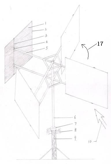
[0020] The self-slowing wind power generator of the present invention comprises a steel frame 9 installed on the ground, a vertically upward pole fixed on the steel frame and a wind wing 1 installed on the top of the pole through a strut 5; the strut 5 is A horizontal cross or triangle, each end of which is vertically equipped with a wind wing 1, and a vertical middle beam 3 is arranged at the transverse third of each wind wing (the position of this middle beam is no more than Two-fifths, but more than one-third of the resistance will be more and more) fixed on the edge of the frame, so that one-third of the wind wing is outside the strut, and the center beam is rotatably installed at the end of the strut A casing 6 is sleeved outside the rod column through a bearing, the strut is fixed on the upper end of the casing, and at least one generator 8 is installed at the corresponding position between the steel frame 9 and the casing 6 . Rectangular wind wing 1 is installed in meta...

Embodiment 2

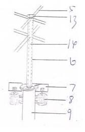
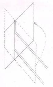
[0037] The self-slowing wind power generator of the present invention comprises a steel frame 9 installed on the ground, a vertically upward pole column fixed on the steel frame and a wind wing 1 installed on the top of the pole column through a strut 5; the strut 5 is A cross bar, the middle part of which is rotatably installed on the top of the pole column, and a plurality of wind wing brackets 18 with the cross bar as the rotating shaft are respectively installed at both ends, and the wind wing 1 is hinged on the horizontal bar of the wind wing support, and the generator 8 is installed in the contact place of strut 5 and pole post top. The rectangular wings are made of canvas mounted within a metal frame. A horizontal middle beam 3 is fixed on the frame limit at the vertical third place of each wind wing, and the middle beam is rotatably installed on the horizontal bar of the wind wing support 18 .


PUM


Abstract

The invention belongs to a wind driven generator, and relates to a self-postponed wind driven generator, which comprises a steel frame arranged on the ground, a post column which is upward vertically and is fixed on the steel frame and wind wings arranged at the top end of the post column by a stay bar, wherein the stay bar is in a horizontal cross or triangular shape, each wind wing is arranged on each end part of the stay bar vertically, and a vertical middle beam is fixed on the edge of a frame at the 1 / 3 position of each wind wing in the lateral direction, so that 1 / 3 part of the wind wing is positioned outside the stay bar; the middle beams are rotationally arranged on the end part of the stay bar; a sleeve is sleeved outside the post column by a bearing; the stay bar is fixed to theupper end of the sleeve; and at least one generator is arranged at the position of the steel frame corresponding to the sleeve. The invention has the advantages that the self-postponed wind driven generator is economic, simple, easy to install and large in generated energy, and the wind wings can be widened and heightened and also can be extended by 1 / 3. The self-postponed wind driven generator integrates the advantages in the conventional windmills and is improved, so the trouble of manufacturing and the difficulty in installation are reduced, and the generated energy is improved greatly.

Description

technical field [0001] The invention belongs to wind power generators, and relates to a self-slowing wind power generator. Background technique [0002] The existing wind generators are unsatisfactory in terms of poor economic benefits, complex manufacturing, complex installation, and insufficient power generation, and need to be improved. Contents of the invention [0003] In order to make up for the deficiencies of the prior art, the present invention provides a self-slowing wind power generator with simple structure, convenient installation and use, and good power generation effect. [0004] The present invention is achieved through the following technical solutions: [0005] The self-slowing wind power generator of the present invention is special in that it includes a steel frame installed on the ground, a vertically upward pole fixed on the steel frame, and a wind wing installed on the top of the pole through a strut; The rod is in the shape of a horizontal cross o...

Claims


Application Information

Patent Timeline
IPC IPC(8): F03D9/00F03D3/00F03D3/06
CPCY02E10/74Y02E10/72Y02P70/50
Inventor 迟秀强
Owner 迟秀强
Why Eureka
Try Eureka