Workpiece pressing device for broaching machine

A technology for pressing devices and workpieces, which is applied in the direction of broaching devices, clamping devices, broaching machines, etc., which can solve problems such as potential safety hazards, workpiece tipping, and inability to ensure uniform pressure on workpieces, so as to improve safety and workpiece pressure. Firm and firm effect

Pending Publication Date: 2020-07-28
ZHEJIANG CHR INTELLIGENT EQUIP
View PDF2 Cites 0 Cited by
  • Summary
  • Abstract
  • Description
  • Claims
  • Application Information

AI Technical Summary

Problems solved by technology

Because the driving device of this type of workpiece pressing device is located on the side, under the action of the driving device, the movement track of the pressing end of the pressing block is an arc, which cannot guarantee uniform pressure on the workpiece (especially the ring workpiece) , the workpiece is prone to tipping due to uneven force, and there are certain safety hazards

Method used


Image

  • Workpiece pressing device for broaching machine
  • Workpiece pressing device for broaching machine
  • Workpiece pressing device for broaching machine

Examples


Embodiment Construction

[0031] The present invention will be further described in detail below in conjunction with the accompanying drawings and embodiments.

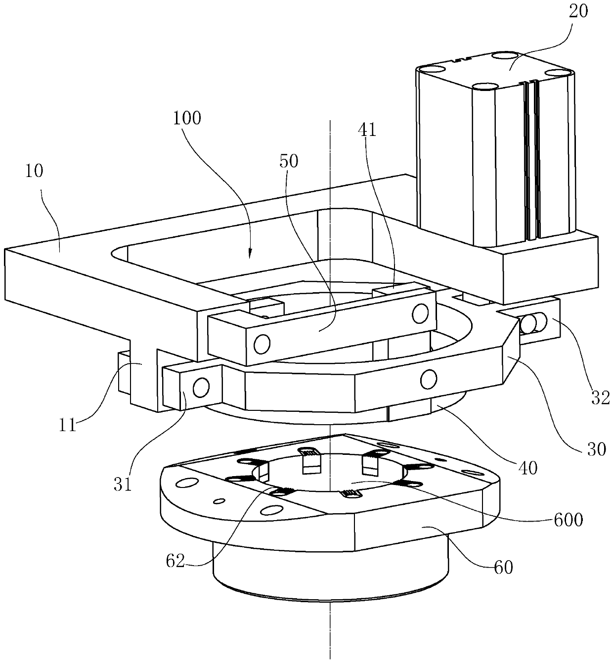
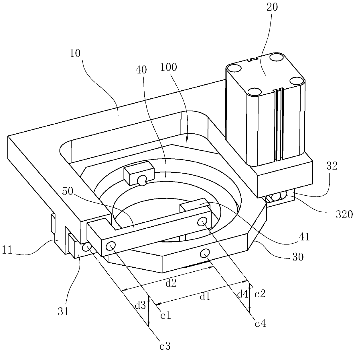
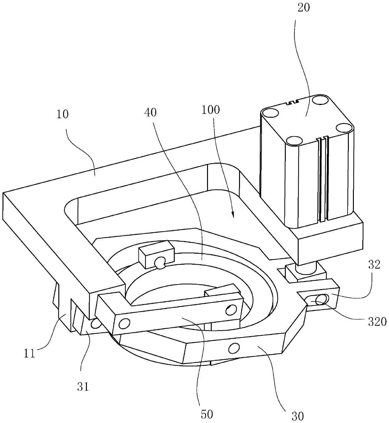
[0032] see Figure 1-Figure 7 , a workpiece pressing device for a broaching machine includes a support frame 10 , a driving device 20 , a connecting sleeve 30 , a pressure ring 40 , at least one rocker arm 50 and a positioning faceplate 60 .

[0033] see Figure 1-Figure 3 , the support frame 10 is fixed relative to the workbench (not shown), specifically located above the workbench. There is a relief space 100 on the support frame 10, specifically, the relief space 100 of the support frame 10 is located above the workpiece placement position of the workbench (taking the internal tooth groove of a ring-shaped workpiece as an example, the workpiece placement position is a central hole structure) , for the broach to pass through. The driving device 20 of this embodiment can be arranged on the support frame 10, specifically, the driving device...


PUM


Abstract

The invention relates to a workpiece pressing device for a broaching machine. The workpiece pressing device comprises a supporting frame, a driving device, a connecting sleeve, a pressing ring, and atleast one rocker arm, wherein the driving device is arranged on one side of a workbench of the broaching machine; the connecting sleeve is rotationally connected to the supporting frame through a first connecting part and is connected with the acting end of the driving device through a second connecting part, and under the action of the driving device, the connecting sleeve can rotate up and downaround the first connecting part relative to the supporting frame; the front side and the rear side of the pressing ring are hinged to the connecting sleeve, and at least one side of the front side and the rear side of the pressing ring is provided with at least one first supporting arm formed by extending upwards; and the number of the at least one rocker arm is correspondingly consistent with the number of the at least one first supporting arm of the pressing ring, the first end of each rocker arm is hinged to the supporting frame, and the second end of each rocker arm is hinged to the endpart of the corresponding first supporting arm of the pressing ring, so that the pressing ring is kept in a horizontal state in the process of moving downwards along with the connecting sleeve. According to the workpiece pressing device, the driving device can be arranged on the side portion of the workbench, the driving device can drive the pressing ring to stably move downwards, and therefore itis guaranteed that a workpiece is evenly stressed.

Description

technical field [0001] The invention relates to the technical field of broaching machines, in particular to a workpiece pressing device for a broaching machine. Background technique [0002] The workpiece pressing device that the existing broaching machine adopts is installed on the front of the machine tool workbench. Classified according to the layout position of the driving device (such as an oil cylinder), there are generally two types, one is directly above the center hole of the workbench where the driving device is directly installed, such as the application number CN201721214236.0 (authorized announcement number CN207189250U) "A Workpiece Pressing Device for Broaching Machines" disclosed in the Chinese utility model patent includes a bracket, a hollow annular oil cylinder and a pressure ring. On the bracket, a pressure ring for pressing the workpiece is provided under the hollow annular oil cylinder, and the pressure ring is driven by the annular piston rod to move ...

Claims


Application Information

Patent Timeline
IPC IPC(8): B23D41/06B23Q3/06B23Q3/08
CPCB23D41/06B23Q3/06B23Q3/08B23Q3/082B23Q2703/04
Inventor 林绿高
Owner ZHEJIANG CHR INTELLIGENT EQUIP
Why Eureka
Try Eureka