Card chip machining equipment

A technology for processing equipment and chips, used in metal processing equipment, grinding/polishing equipment, manufacturing tools, etc., and can solve problems such as temperature rise, insufficient temperature recovery, deformation, etc.

Inactive Publication Date: 2020-07-28
吴学彪
View PDF11 Cites 2 Cited by
  • Summary
  • Abstract
  • Description
  • Claims
  • Application Information

AI Technical Summary

Problems solved by technology

[0006] In order to solve the above technology, when the friction head is placed on the side of the card chip for high-speed rotation, the temperature will rise, and its body is thinner, and it is easier to stick to the surface of the platform in a sagging state, and it will return to temperature when it is picked up later. Not enough will cause deformation problems

Method used


Image

  • Card chip machining equipment
  • Card chip machining equipment
  • Card chip machining equipment

Examples


Embodiment 1

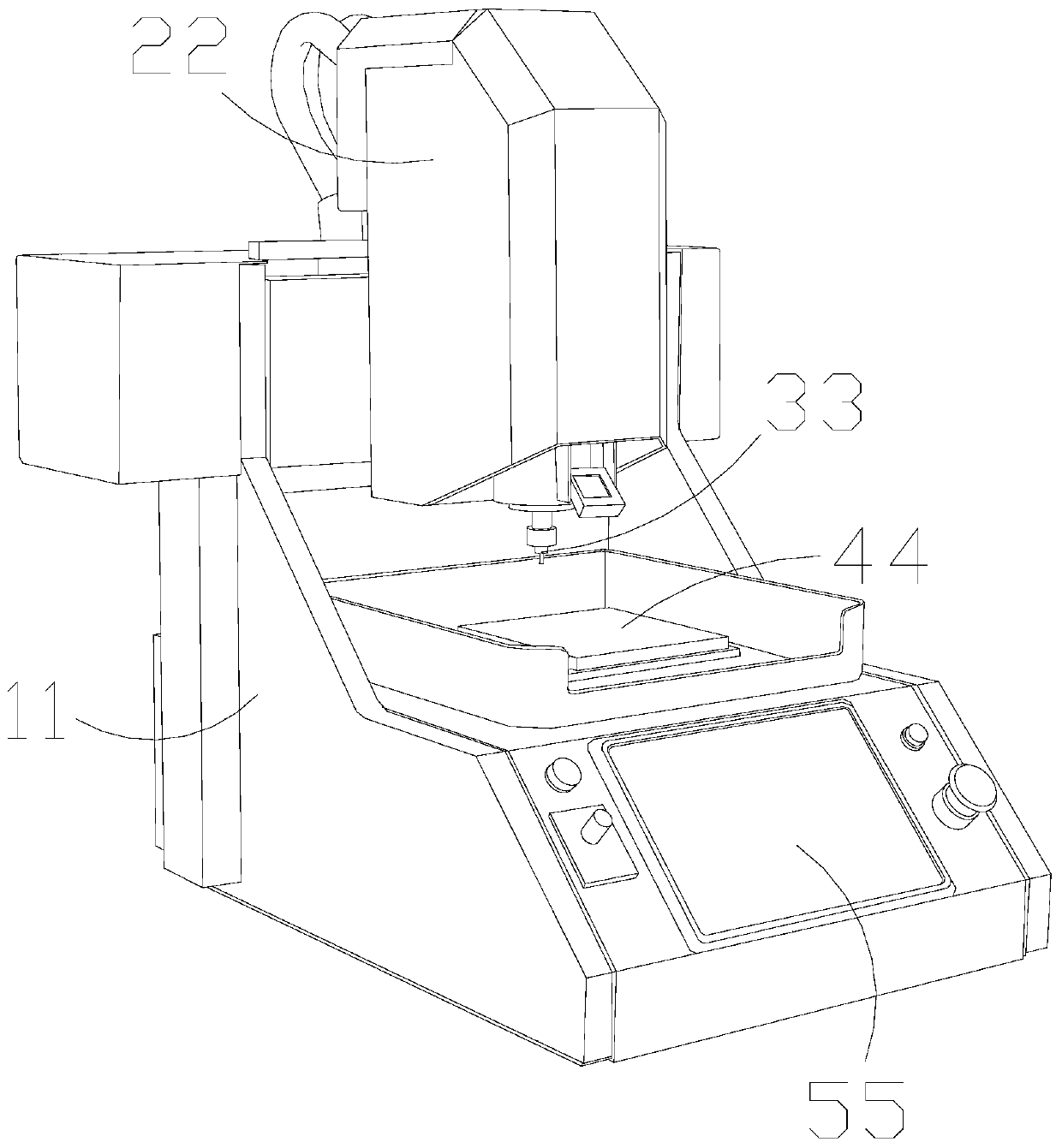
[0031] As attached figure 1 Attached Figure 5 Shown:

[0032] The present invention provides a card chip processing equipment, the structure of which includes a main controller 11, a control head 22, a processing head 33, an operating table 44, and a control panel 55.

[0033] The control panel 55 and the main control machine 11 are an integrated structure, the operation table 44 is welded to the upper surface of the main control machine 11, and the upper end of the processing head 33 penetrates the control head 22.

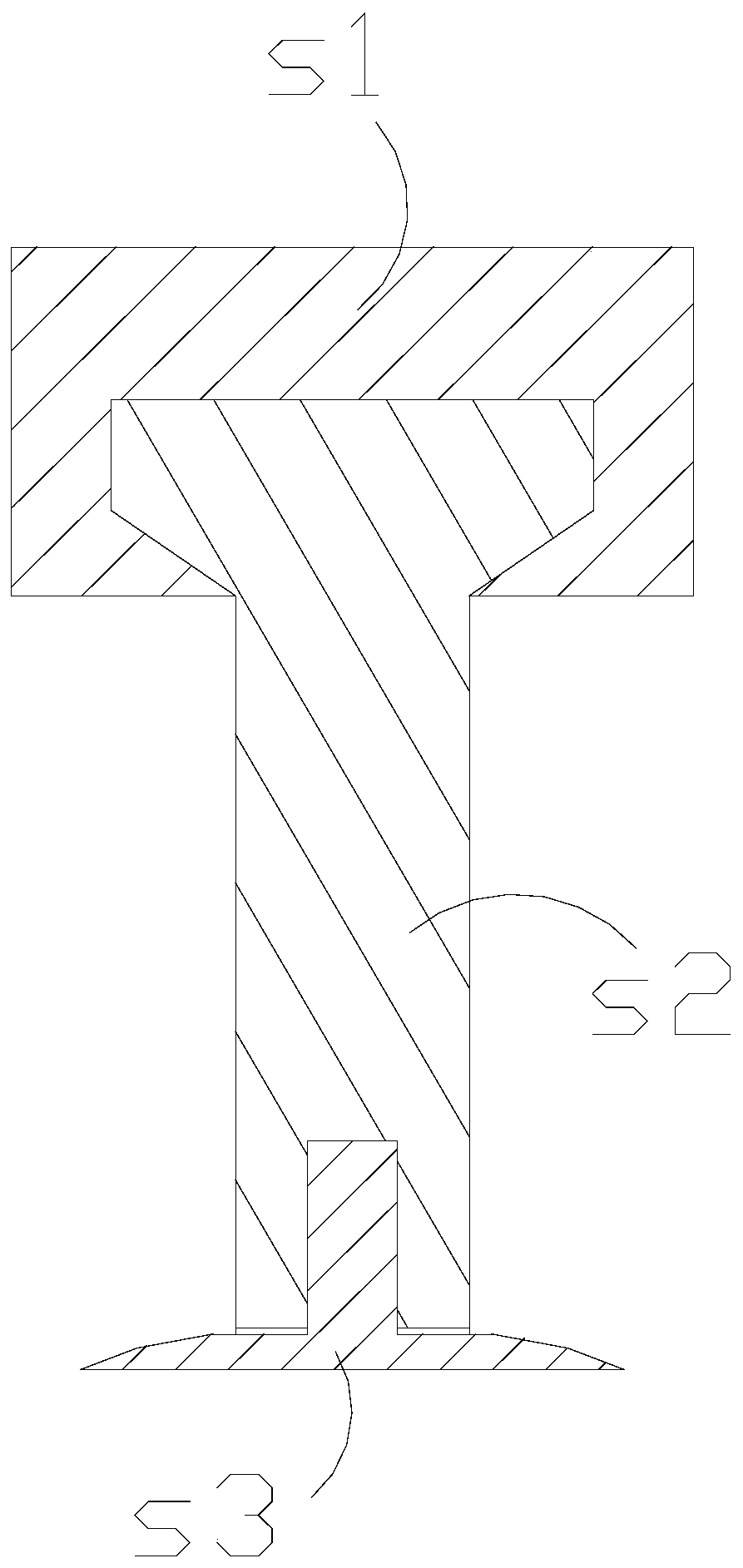
[0034] Wherein, the processing head 33 includes a hub 1, a main rotating rod 2, a bottom bracket 3. The upper end of the main rotating rod 2 is embedded in the hub 1, and a bottom bracket 3 is installed inside the end of the main rotating rod 2 away from the hub 1 , The outer surface of the sleeve head 1 is a square structure, and the inside is in the form of a five-sided inner groove. The sleeve head 1 controls the installation and movable positions of the lower end j...

Embodiment 2

[0041] As attached Image 6 Attached Picture 8 Shown:

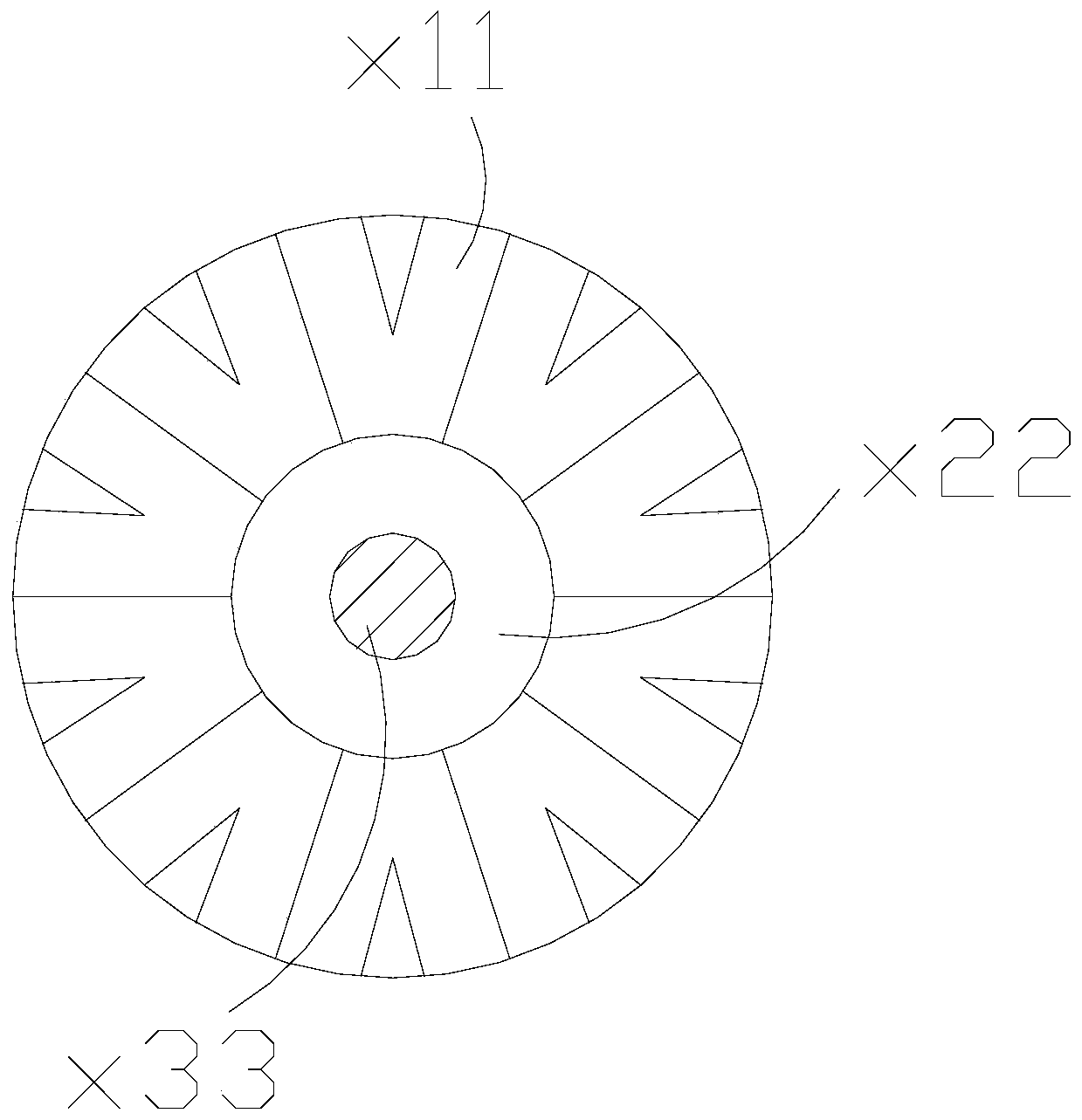
[0042] Wherein, the main rotating rod 2 includes a rotating edging 101 and a medium hard body 202, the rotating edging 101 abuts on the outer surface of the medium hard body 202, the rotating edging 101 has a triangular structure, and the rotating edging 101 It can force external objects as a whole, and when there is a single point of force, the whole line will swing.

[0043] Wherein, the rotating edging 101 includes a total force side 11 and a cohesive angle 22. The total force side 11 is embedded in the cohesive angle 22. There are four cohesive angles 22. The total force side 11 It is a trapezoidal structure. The total force side 11 receives the force at one point as a whole, and the force angle 22 gathers the force at one end to guide it in one direction.

[0044] Wherein, the cohesive angle 22 includes an inner divergence angle 11, a support head 22, and a barrier layer 33. The force barrier layer 33 and the inner diver...


PUM


Abstract

The invention discloses card chip machining equipment. The equipment structurally comprises a main control machine, a control head, a machining head, an operating table and a control panel, wherein the control panel and the main control machine are integrated, the operating table is welded on the upper surface of the main control machine, and a bottom support is placed on the lower surface of an object; through rotation of the upper portion, an interlayer fixes the hard moving force on the object, supporting corners are dragged to carry out buffer movement on the object, when the external force moves along the periphery, the change of the rotating speed following the object is reduced when the object is trimmed, and the contact surface with the operating table is spaced, and thus the object cannot stick to a table top due to the excessive trimming temperature; the interior is subjected to force supporting and fixing through a middle hard body; due to the fact that a total force edge ofthe outer layer of a rotating grinding edge is integrated into a whole, force applying in a certain area is carried out on an internal force gathering corner, an abutting supporting head mainly bearsthe application force of the outer side, and when the equipment machines the object, unit force bearing is changed to multi-point force bearing, and abutted parts are trimmed.

Description

Technical field [0001] The invention belongs to the field of chips, and more specifically, relates to a card chip processing equipment. Background technique [0002] When the card chip is processed, the card chip will have burrs that need to be processed. When trimming the edges and corners, the friction head is rotated to slightly move around the card chip. [0003] Based on the above findings, the present inventors found that the existing card chip processing equipment mainly has the following shortcomings, such as: [0004] In the process of high-speed rotation of the friction head on the side of the card chip, the temperature will rise, the body is thin, and it is easier to sag on the surface of the platform. Insufficient temperature will cause deformation during subsequent picking. . [0005] Therefore, it is necessary to provide a card chip processing equipment. Summary of the invention [0006] In order to solve the above-mentioned technology, the temperature will increase whe...

Claims


Application Information

Patent Timeline
IPC IPC(8): B24B9/02B24B41/02H01L21/67
CPCB24B9/02B24B41/02H01L21/67092
Inventor 吴学彪
Owner 吴学彪
Why Eureka
Try Eureka