Construction method of underground diaphragm wall

A technology of underground continuous wall and construction method, which is applied in excavation, sheet pile wall, infrastructure engineering and other directions, can solve the problems of waterproof and easy leakage of the underground connecting wall of the easy-to-collapse groove, and achieves the enhancement of the wall protection ability and the improvement of the weak waterproof parts. , reduce the effect of disturbance

Inactive Publication Date: 2020-07-28
珠海十字门中央商务区建设控股有限公司
View PDF4 Cites 3 Cited by
  • Summary
  • Abstract
  • Description
  • Claims
  • Application Information

AI Technical Summary

Problems solved by technology

[0005] The purpose of the present invention is to provide a construction method for an underground diaphragm wall, by adopting a partition wall composed of double rows of three-axis stirring piles, and adopting double anti-seepage measures at the joints of the underground connecting wall to solve the problem of silt geological collapse and underground connection Technical Problems of Easy Leakage at Weak Waterproof Parts of Walls

Method used

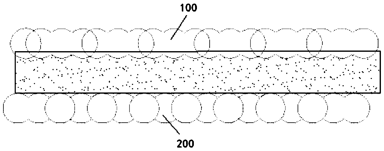
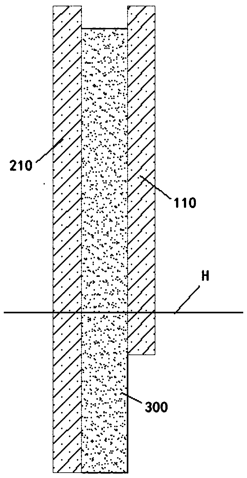
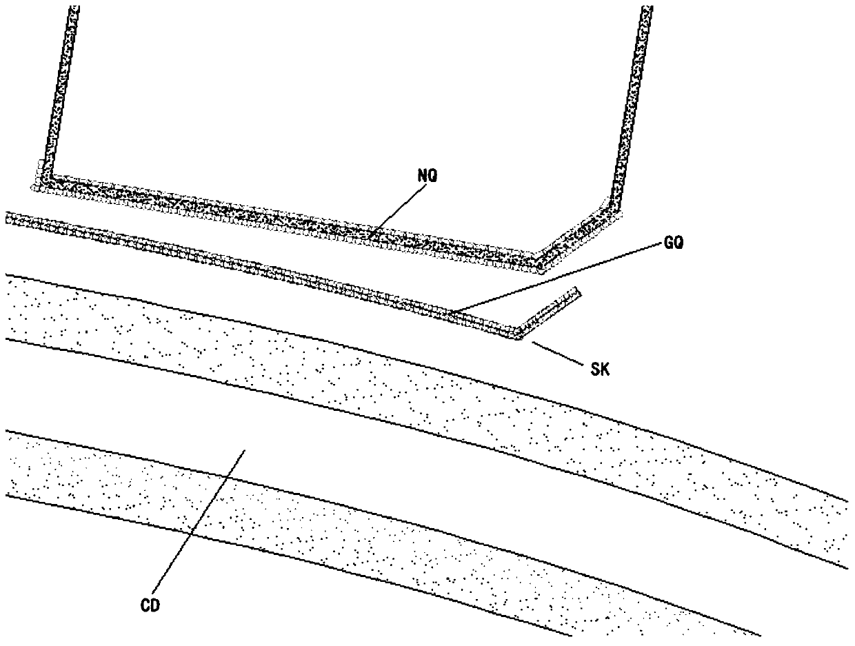

Image

  • Construction method of underground diaphragm wall
  • Construction method of underground diaphragm wall
  • Construction method of underground diaphragm wall

Examples


Embodiment Construction

[0046] The technical solutions of the present invention will be clearly and completely described below in conjunction with the accompanying drawings. Apparently, the described embodiments are some of the embodiments of the present invention, but not all of them. Based on the embodiments of the present invention, all other embodiments obtained by persons of ordinary skill in the art without making creative efforts belong to the protection scope of the present invention.

[0047] In the description of the present invention, it should be noted that the terms "center", "upper", "lower", "left", "right", "vertical", "horizontal", "inner", "outer" etc. The indicated orientation or positional relationship is based on the orientation or positional relationship shown in the drawings, and is only for the convenience of describing the present invention and simplifying the description, rather than indicating or implying that the referred device or element must have a specific orientation, ...


PUM


Abstract

The invention aims at providing a construction method of an underground diaphragm wall. A separation wall composed of double rows of three-axis mixing piles is adopted, and double anti-seepage measures are adopted at a joint of the underground diaphragm wall, so that the technical problems that a groove is prone to collapsing in sludge geology, and leakage is prone to occurring at a waterproof weak position of the underground diaphragm wall are solved. The method comprises the following steps of building the separation wall composed of the three-axis mixing piles; reinforcing two sides of a construction position of the underground diaphragm wall by adopting the three-axis mixing piles; constructing the underground diaphragm wall by adopting a groove-jumping construction operation mode, a slurry retaining wall construction process and an underwater concrete pouring construction process, wherein a joint part of the underground diaphragm wall is the I-shaped steel joint; and treating a groove section joint by adopting a high-pressure jet grouting pile. Through the method disclosed by the invention, the construction problems of large disturbance deformation, easy groove collapse and the like of a sludge stratum can be effectively solved.

Description

technical field [0001] The invention relates to the technical field of diaphragm wall construction, in particular to an underground diaphragm wall construction method. Background technique [0002] The underground diaphragm wall in the prior art is a construction method developed in the construction of deep foundations. It uses special trenching equipment to excavate trenches according to the designed width, length and depth along the deep foundation or the periphery of underground structures with thixotropic mud retaining wall. After the trench section is formed, a reinforcement cage is placed in the trench. Concrete is poured using the conduit method to form a unit trough section and concrete wall, so as to continue digging and pouring concrete construction, and connect the unit walls one by one by a certain joint method to form a continuous underground reinforced concrete wall or concrete wall. The curtain is used as an underground wall structure for anti-seepage, soil r...

Claims


Application Information

Patent Timeline
Patent Type & Authority Applications(China)
IPC IPC(8): E02D5/20E02D5/46E02D15/04E02D17/04E02D19/18
CPCE02D5/20E02D5/46E02D15/04E02D17/04E02D19/18
Inventor 周吉林米向东范银忠钟畅迁刘峰
Owner 珠海十字门中央商务区建设控股有限公司
Why Eureka
Try Eureka