
Earth rotation correction method and system under laboratory coordinate system

A technology of earth rotation and coordinate system transformation, applied in the field of simulation, can solve the problems of rotation angular velocity distortion, earth rotation inconsistency between heaven and earth, etc., achieve the effect of correcting the influence of earth rotation and solving the problem of measuring the distortion of earth rotation angular velocity

Active Publication Date: 2020-07-28
BEIJING SIMULATION CENT
View PDF9 Cites 1 Cited by
  • Summary
  • Abstract
  • Description
  • Claims
  • Application Information

AI Technical Summary

Problems solved by technology

[0004] For this reason, the embodiment of the present application provides a method and system for correcting the earth's rotation in the laboratory coordinate system, which considers the inconsistency of the earth's rotation between the hardware-in-the-loop simulation and the actual flight of the missile, and solves the problem of inertial measurement device measurement in the laboratory environment. Earth rotation angular velocity distortion issue, corrected for Earth rotation effects where the launch location and lab didn't match

Method used


Image

  • Earth rotation correction method and system under laboratory coordinate system
  • Earth rotation correction method and system under laboratory coordinate system
  • Earth rotation correction method and system under laboratory coordinate system

Examples


Embodiment Construction

[0039] The implementation mode of the present invention is illustrated by specific specific examples below, and those who are familiar with this technology can easily understand other advantages and effects of the present invention from the contents disclosed in this description. Obviously, the described embodiments are a part of the present invention. , but not all examples. Based on the embodiments of the present invention, all other embodiments obtained by persons of ordinary skill in the art without making creative efforts belong to the protection scope of the present invention.

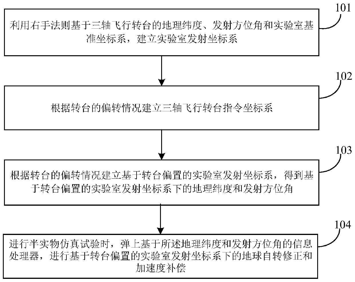
[0040] figure 1 It shows a method for correcting the earth's rotation in a laboratory coordinate system provided by the embodiment of the present application, and the method includes the following steps:

[0041] Step 101: Use the right-hand rule based on the geographic latitude λ of the three-axis flight turntable eT , launch azimuth A tT and the laboratory reference coordinate system to esta...


PUM


Abstract

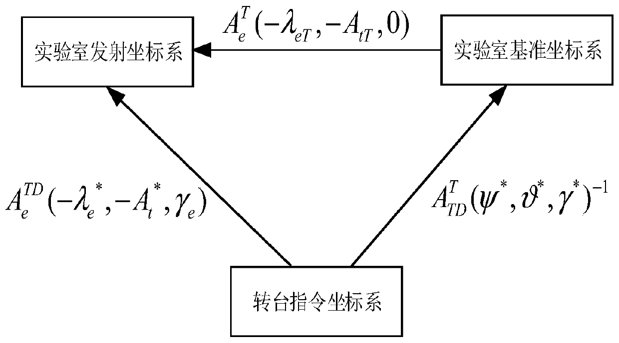
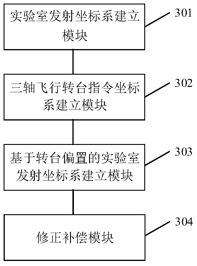
The embodiment of the invention discloses an earth rotation correction method and system under a laboratory coordinate system. The method comprises the steps of establishing a laboratory launch coordinate system based on geographic latitude lambda <eT> and launch azimuth A <tT> of a three-axis flight rotary table and a laboratory reference coordinate system through a right-hand rule; establishinga three-axis flight rotary table instruction coordinate system according to the bias condition of the rotary table; establishing a laboratory launch coordinate system based on rotary table bias according to the bias condition of the rotary table to obtain geographic latitude lambda < e > <*> and launch azimuth A < t > <*> under the laboratory launch coordinate system based on rotary table bias; and carrying out earth rotation correction and acceleration compensation under the laboratory launch coordinate system based on rotary table bias through a missile-borne information processor based on the geographic latitude lambda < e > <*> and the launch azimuth A < t > <*> during semi-physical simulation test. According to the method and system, the problem that the distortion occurs when the earth rotation angular velocity is measured through an inertial measurement unit in a laboratory environment is solved, and the earth rotation influence caused by mismatching between a launching site anda laboratory is avoided.

Description

technical field [0001] The embodiments of the present application relate to the field of simulation technology, and in particular to a method and system for correcting the earth's rotation in a laboratory coordinate system. Background technique [0002] Hardware-in-the-loop simulation is an important verification method for missile guidance and control system development, algorithm prediction, parameter optimization and flight test prediction. During the flight of the missile, the inertial measurement device is used to measure the angular velocity information and acceleration information of the missile, and send them to the information processor on the missile for guidance circuit calculation. The on-board information processor constructs a launch coordinate system based on the bound launch location and launch azimuth, and uses the measurement information of the inertial measurement device to perform earth rotation correction and acceleration compensation. [0003] In the h...

Claims


Application Information

Patent Timeline
Patent Type & Authority Applications(China)
IPC IPC(8): F41G3/32
CPCF41G3/32
Inventor 王晓雷李响刘柏廷张宇
Owner BEIJING SIMULATION CENT
Learn More