
Fire combustion and ventilation control system for spiral tunnel group

A technology of ventilation control system and tunnel group, applied in the field of tunnel ventilation and smoke exhaust

Active Publication Date: 2020-07-28
HEFEI UNIV OF TECH
View PDF6 Cites 6 Cited by
  • Summary
  • Abstract
  • Description
  • Claims
  • Application Information

AI Technical Summary

Problems solved by technology

[0006] The technical problem to be solved by the present invention is the ventilation and smoke control strategy for the spread of fire smoke in various situations of spiral tunnel groups. Ventilation and smoke control simulation of smoke spread, prediction of smoke flow law in spiral tunnel group fires, temperature changes in tunnels, critical wind speed and other fire parameters

Method used

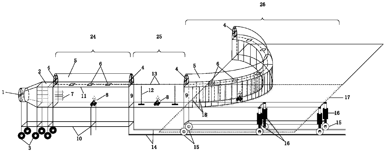
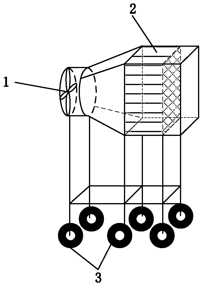
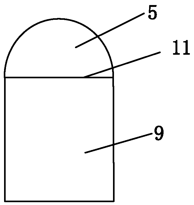

Image

  • Fire combustion and ventilation control system for spiral tunnel group
  • Fire combustion and ventilation control system for spiral tunnel group
  • Fire combustion and ventilation control system for spiral tunnel group

Examples


specific Embodiment 1

[0051] Specific Example 1: Carry out experimental research on flue gas channeling in a group of spiral tunnels.

[0052] For the spiral tunnel group, whether the smoke can spread from one tunnel to the adjacent tunnel mainly depends on the longitudinal wind of the tunnel, the heat release rate of the fire source, the aspect ratio of the tunnel, the slope and the distance between the tunnel groups. spacing, and the size of the tunnel curve radius, etc. Based on the theoretical analysis of the Froude number, the Froude number represents the relative competition between the inertial force formed by the longitudinal wind in the tunnel and the thermal buoyancy of the fire source. In the experiment, the control variable method was used to carry out multiple sets of simulation experiments, and the experimental results of the flue gas channeling from one tunnel to the other in the spiral tunnel group were obtained. The channeling of the flue gas needs to be determined by the laser she...

specific Embodiment 2

[0053] Specific Example 2: Carry out experimental research on flue gas control of spiral tunnel groups.

[0054] Due to the existence of the slope of the spiral tunnel, there will be a chimney effect; at the same time, due to the existence of the spiral, the flue gas will also produce a curved motion. This poses a challenge for smoke control in tunnel fires. In view of the experimental research on smoke control of spiral tunnel groups, it is planned to carry out comparative research on working conditions of tunnel groups with different slopes and curvature radii, different longitudinal wind sizes, fire source power and distance between tunnel groups, and summarize the smoke control schemes under different conditions. Such as critical wind speed evolution model, smoke stratification stability determination criteria, etc. At the same time, guide the evacuation route correctly to minimize the impact of fire smoke on the evacuation of personnel and property.


PUM


Abstract

The invention discloses a fire combustion and ventilation control system of a spiral tunnel group. The spiral tunnel group comprises a straight tunnel and a spiral tunnel. A longitudinal ventilation device is arranged at a left port of the straight tunnel and can be adjusted according to a required longitudinal wind amount, and the ventilation direction can be changed. The position of a fire source is variable, and fires in the straight tunnel, the spiral tunnel and a connection transition section can be simulated. The spiral tunnel is composed of tunnel unit sections, the length can be increased or decreased, and the spiral radius can be selected on a tunnel moving platform according to needs. The tunnel inclination angle is adjusted through a jack. Fire smoke enters a centralized smoke exhaust pipeline through a centralized smoke exhaust port of the tunnel ceiling and then is exhausted through a centralized smoke exhaust fan arranged at the port of the pipeline. Through simulation ofthe system, smoke diffusion parameters of different fire smoke of the spiral tunnel group can be acquired, and the purpose of seeking an efficient smoke control method is achieved.

Description

technical field [0001] The invention belongs to the related technical field of tunnel ventilation and smoke exhaust, in particular to a fire combustion and ventilation control system for spiral tunnel groups. Background technique [0002] With the rapid development of my country's social economy and the increasing demand for national transportation, the construction of tunnels such as roads and railways is also gradually increasing, and the problem of tunnel fires is also subject to more and more problems. Highway tunnel fires cause great harm, especially for long and extra-long tunnels. After a fire occurs, there will be a large amount of smoke in the tunnel, low visibility, slow heat dissipation, and high temperature. Especially when a fire occurs in a highway tunnel with a large traffic flow, evacuation is difficult due to the low visibility in the tunnel. Therefore, smoke prevention and exhaust in tunnel fires are an important part of ventilation design. In recent years...

Claims


Application Information

Patent Timeline
IPC IPC(8): G09B25/04G09B25/00
CPCG09B25/04G09B25/00
Inventor 唐飞朱元涛赵尊信王强董满生侯超群
Owner HEFEI UNIV OF TECH
Learn More