Overhead bare conducting wire insulating coating robot

A wire insulation and insulation coating technology, which is applied in the direction of insulation/armored cable repair equipment, etc., can solve the problems of large volume, complicated and inconvenient lifting process, and increased construction work time, etc.

Pending Publication Date: 2020-07-28
安捷电维智能科技研究院(广州)有限公司
View PDF0 Cites 3 Cited by
  • Summary
  • Abstract
  • Description
  • Claims
  • Application Information

AI Technical Summary

Problems solved by technology

[0003] Most of the existing overhead bare wire insulation coating robots are integrated. The entire overhead bare wire insulation coating robot has the problems of large size and heavy weight. In actual work, other lifting equipment is needed to lift the entire overhead bare wire. The wire insulation coating robot is lifted to the height of the overhead bare wire. The lifting process is cumbersome and inconvenient. At the same time, it requires a lot of manpower and material resources. The construction cost is reduced, which affects the economic benefits of the insulation transformation of overhead bare conductors

Method used


Image

  • Overhead bare conducting wire insulating coating robot
  • Overhead bare conducting wire insulating coating robot
  • Overhead bare conducting wire insulating coating robot

Examples


Embodiment 1

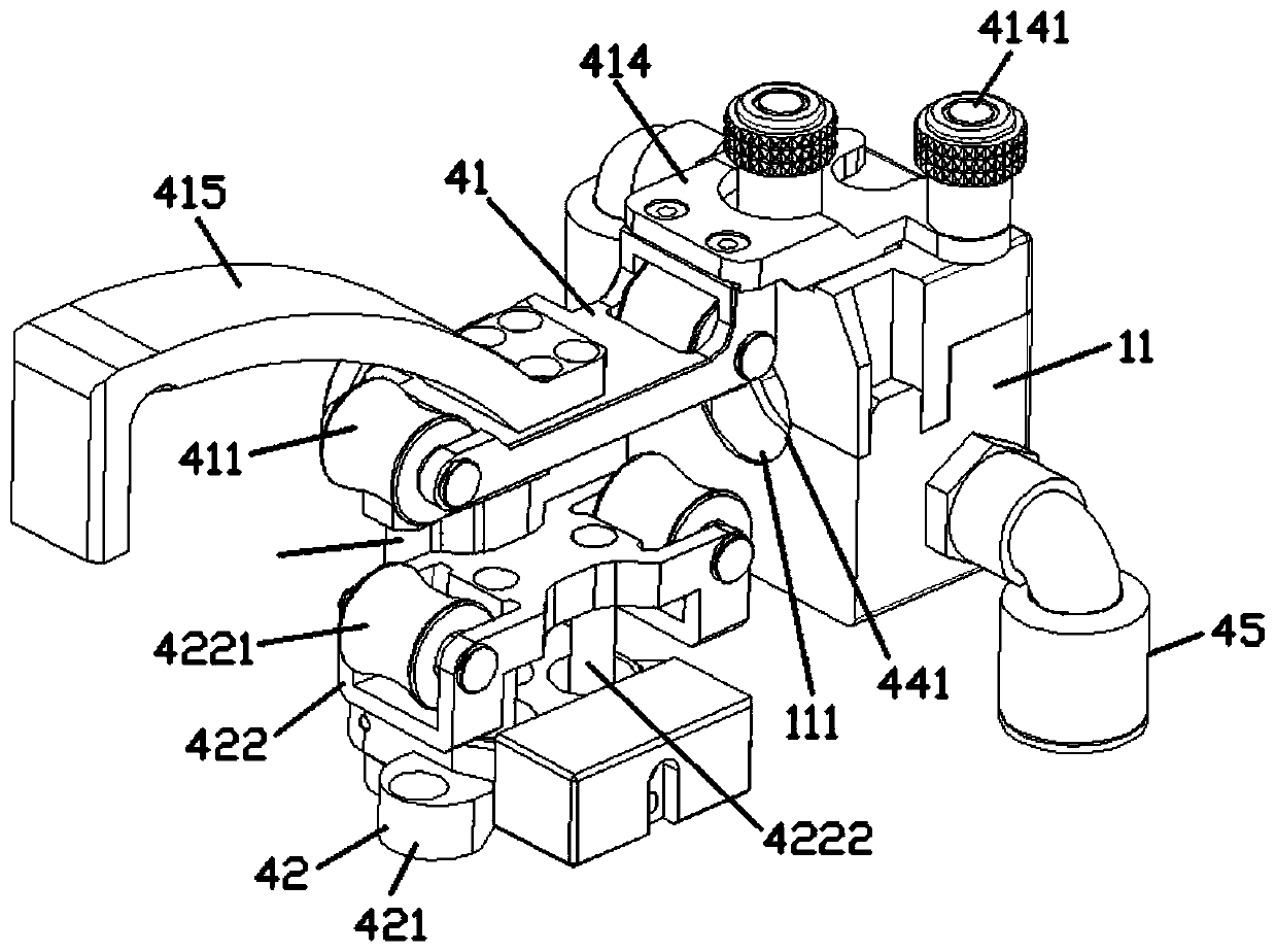
[0060] image 3 It is the first three-dimensional structural schematic diagram of the insulating coating module in the first embodiment of the present invention, Figure 4 It is a schematic diagram of the second three-dimensional structure of the insulating coating module in Embodiment 1 of the present invention, Figure 5 It is a schematic diagram of the three-dimensional structure of the fixed pallet in Embodiment 1 of the present invention.

[0061] In the first embodiment, the insulation coating module 1 further includes a fixed bracket 41 , a sliding assembly 42 and a positioning guide rod 43 .

[0062] The fixed pallet 41 is connected to the front side of the insulating coating die head 11, and a plurality of fixed positioning wheels 411 are sequentially hinged in the fixed pallet 41 along the straight direction of the cable channel 111, and the The fixed pallet 41 is provided with a pallet sliding hole 412 and a plurality of sliding guide rods 413 along the vertical d...

Embodiment 2

[0079] Figure 7 It is the first three-dimensional structural schematic diagram of the insulating coating module in the second embodiment of the present invention, Figure 8 It is a schematic diagram of the second three-dimensional structure of the insulating coating module in the second embodiment of the present invention.

[0080] In the second embodiment, the insulation coating module 1 further includes a support assembly 51 and a first mold driving device 54 , and the insulation coating die head 11 includes a first mold 52 and a second mold 53 .

[0081] The support assembly 51 includes a support mounting plate 511 and a module bottom plate 512, the module bottom plate 512 is connected to one side of the support mounting plate 511, and a plurality of The first positioning wheel 5111, the module bottom plate 512 is provided with a plurality of horizontal guide pins 5121 perpendicular to the first horizontal line.

[0082] The inner surface of the first mold 52 is provided...

Embodiment 3

[0103] Figure 9 It is a schematic diagram of the first three-dimensional structure of the insulating coating module in the third embodiment of the present invention, Figure 10 It is a schematic diagram of the second three-dimensional structure of the insulating coating module in the third embodiment of the present invention.

[0104] In the third embodiment, the insulation coating module 1 further includes a support frame 61 and a second mold driving device 62 , and the insulation coating die head 11 includes a third mold 63 and a fourth mold 64 .

[0105] A plurality of second positioning wheels 611 are sequentially hinged on the top of the support frame 61 along the first straight line.

[0106] The inner surface of the third mold 63 is provided with a third groove 631, and the outer surface of the third mold 63 is provided with a third coating hole 632 communicating with the third groove 631; the fourth mold The inner surface of the mold 64 is provided with a fourth gro...


PUM


Abstract

The invention discloses an overhead bare conducting wire insulating coating robot, which comprises an insulating coating module, an active driving assembly and a gluing module, wherein the active driving assembly comprises an active driving rack, winding shafts are hinged to the left side and the right side of the active driving rack respectively, the winding shafts are driven by a winding shaft driving device to rotate, gluing connecting parts are arranged on the left side and the right side of the gluing module correspondingly, and the winding shafts on the left side and the right side of the active driving rack are connected with the gluing connecting parts on the left side and the right side of the gluing module through connecting ropes correspondingly. In the embodiment of the invention, the whole overhead bare conducting wire insulating coating robot can be lifted to the height of the overhead bare conducting wire without other lifting equipment, so that the lifting process is simple and convenient, a large amount of manpower and material resources do not need to be consumed, the construction operation time is shortened, the construction cost is reduced, and the operation efficiency and economic benefits of overhead bare conducting wire insulating transformation are guaranteed.

Description

technical field [0001] The invention relates to the technical field of insulation coating for overhead bare wires, in particular to an insulation coating robot for overhead bare wires. Background technique [0002] In my country's power transmission, a considerable part depends on the transmission of overhead bare wires. However, the contradiction between buildings and lush green areas and overhead bare wires has become increasingly prominent, often causing accidents. The effective guarantee of stable performance is also the inevitable trend of the expansion of the power grid business. The overhead bare wire insulation coating robot can automatically walk on the overhead bare wire to complete the insulation transformation of the overhead bare wire, which can effectively solve the problem of trees in the city. And the problem that it is difficult to carry out insulation transformation of overhead bare wires in densely populated areas and special environments, not only greatly r...

Claims


Application Information

Patent Timeline
Patent Type & Authority Applications(China)
IPC IPC(8): H02G1/16
CPCH02G1/16
Inventor 李駪皓
Owner 安捷电维智能科技研究院(广州)有限公司
Why Eureka
Try Eureka