Compressed air supply installation for operating pneumatic installation, method and vehicle

A technology of compressed air and facilities, applied in the direction of vehicle springs, vehicle parts, transportation and packaging, etc., to achieve the effect of reducing dependence

Active Publication Date: 2020-07-28
WABCO GMBH
View PDF7 Cites 0 Cited by
  • Summary
  • Abstract
  • Description
  • Claims
  • Application Information

AI Technical Summary

Problems solved by technology

[0008] These concepts, although advantageous for pressure-holding pneumatic devices, still need to be further improved, especially in terms of their compactness and simple construction.

Method used


Image

  • Compressed air supply installation for operating pneumatic installation, method and vehicle
  • Compressed air supply installation for operating pneumatic installation, method and vehicle
  • Compressed air supply installation for operating pneumatic installation, method and vehicle

Examples


Embodiment Construction

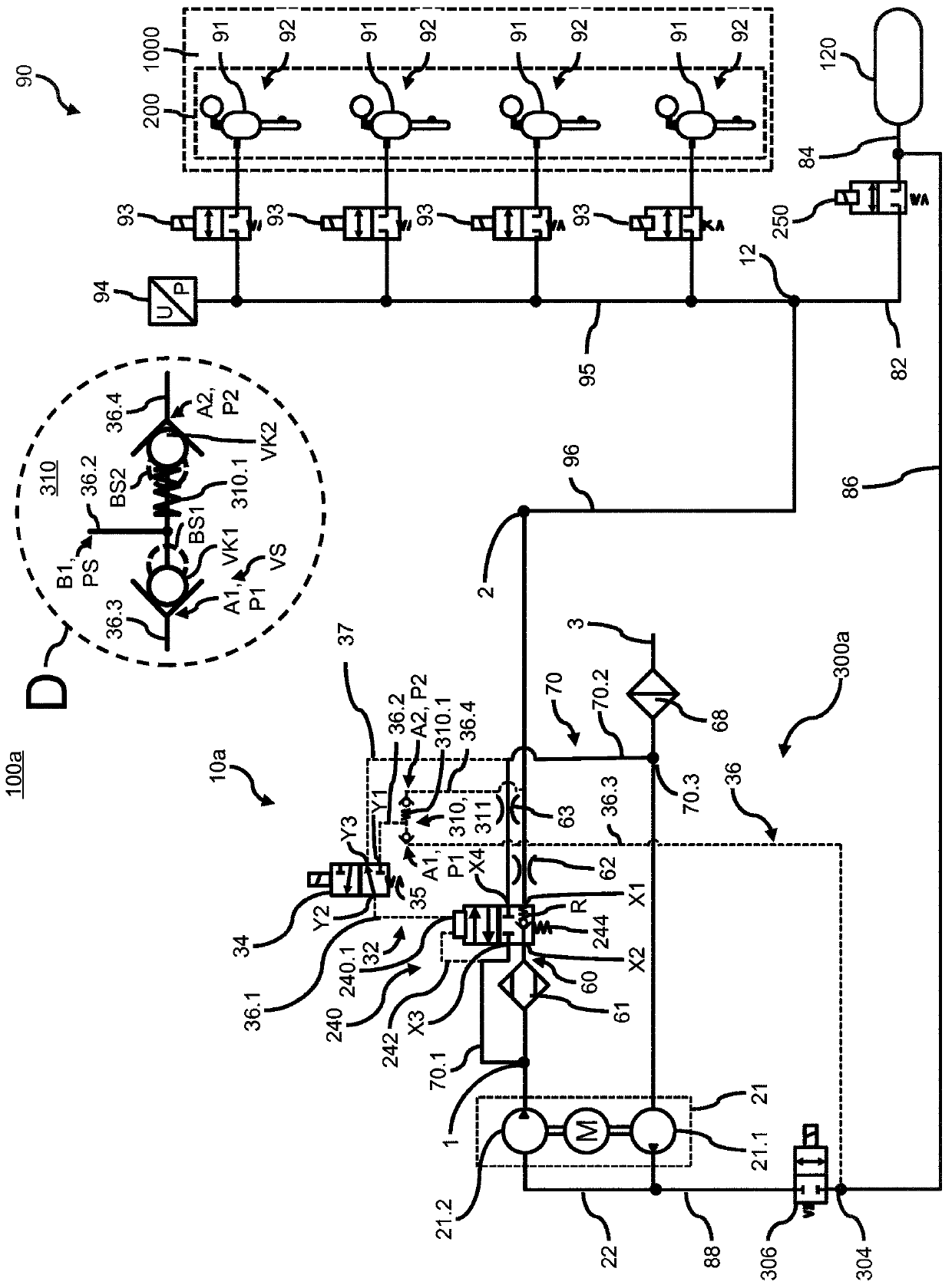
[0037] figure 1 A preferred embodiment of a pneumatic system 100a is shown with a compressed air supply system 10a and an air spring system 90 for the symbolically shown vehicle suspension of a vehicle 1000 not shown in detail. The compressed air supply system 10 a has a compressed air supply 1 , a compressed air connection 2 leading to the air spring system 90 and a vent connection 3 leading to the surrounding environment. Furthermore, the compressed air supply installation 10 a also includes a pneumatic main line 60 between the compressed air supply 1 and the compressed air connection 2 .

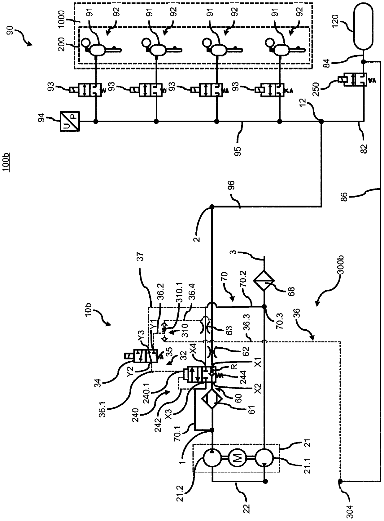
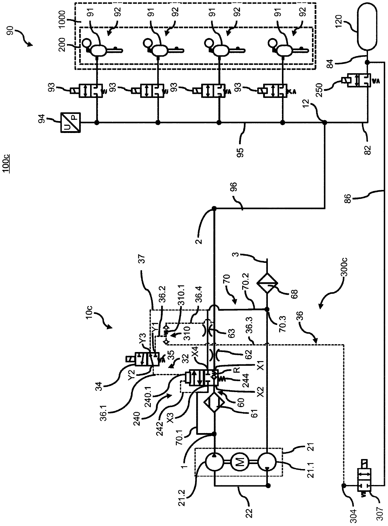
[0038] This and the principle instructions described below for constructing a pneumatic system with compressed air supply system 10 a and pneumatic system 90 also apply to Figures 1 to 3 A variant of a pneumatic system 100 a , 100 b , 100 c with a corresponding compressed air supply 10 a , 10 b , 10 c is shown. For the sake of simplicity, it is meaningful and expedient to use the same ...


PUM


Abstract

The invention relates to a compressed air supply installation (10a, 10b, 10c) for operating a pneumatic installation (90) in a pneumatic system (100a, 100b, 100c) of a vehicle (1000), comprising a compressed air supply (1); a compressed air connection (2) to the pneumatic installation (90); a vent connection (3) to the environment; a pneumatic main line (60) between the compressed air supply (1) and the compressed air connection (2), which comprises an air dryer (61); a vent valve (240), which is arranged on the pneumatic main line (60) and is designed as a pilot valve, having a pilot connection (240.1), a compressor (21) having at least one compressor stage (21.1, 21.2), in addition to the pneumatic main line (60), having a pilot valve (34) and a pneumatic pilot control channel (32), which pneumatically connects the pilot valve (34) to the pilot connection (240.1) of the vent valve (240).

Description

technical field [0001] The invention relates to a compressed air supply for operating a pneumatic system in a pneumatic system of a vehicle, the compressed air supply having: a compressed air supply; a compressed air connection to the pneumatic system; an air discharge connection to the surrounding environment ; The pneumatic main line between the compressed air supply and the compressed air connection, the pneumatic main line has an air dryer; the air release valve, which is arranged on the pneumatic main line and is configured as a pre-control valve, has a pre-control connection ;compressor with at least one compressor stage; in addition to the pneumatic main circuit, it also has a pilot control valve and a pneumatic pilot control channel, which pneumatically connects the pilot control valve to the pilot control interface of the purge valve stand up. The invention also relates to a corresponding vehicle and method. Background technique [0002] Compressed air supply inst...

Claims


Application Information

Patent Timeline
Patent Type & Authority Applications(China)
IPC IPC(8): B60G17/052
CPCB60G17/0523B60G2500/2044B60G17/052B60G2202/152B60G2202/154
Inventor 约尔格·迈尔
Owner WABCO GMBH
Why Eureka
Try Eureka