Industrial furnace hearth cooling device

A technology of cooling device and industrial furnace, applied in furnace cooling, furnace, furnace components and other directions, can solve problems such as reducing work efficiency, inability to rapidly cool inside the furnace, and achieve the effect of increasing stability

Inactive Publication Date: 2017-08-08
CHANGXING CAZENOVE FUNANCE IND CO LTD
View PDF1 Cites 0 Cited by
  • Summary
  • Abstract
  • Description
  • Claims
  • Application Information

AI Technical Summary

Problems solved by technology

[0003] The object of the present invention is to provide a furnace cooling device for an industrial furnace, which has the advantages of rapidly cooling the interior of the industrial furnace and improving work efficiency, and solves the problem that the furnace cannot be cooled rapidly and the work efficiency is reduced

Method used


Image

  • Industrial furnace hearth cooling device
  • Industrial furnace hearth cooling device
  • Industrial furnace hearth cooling device

Examples


Embodiment Construction

[0019] (In the description of the present invention, it should be understood that the terms "center", "longitudinal", "lateral", "length", "width", "thickness", "upper", "lower", "front", "Back", "Left", "Right", "Vertical", "Horizontal", "Top", "Bottom", "Inner", "Outer", "Clockwise", "Counterclockwise" etc. Or the positional relationship is based on the orientation or positional relationship shown in the drawings, only for the convenience of describing the present invention and simplifying the description, rather than indicating or implying that the device or element referred to must have a specific orientation, be constructed and operated in a specific orientation , so it should not be construed as a limitation of the present invention.

[0020] In addition, the terms "first" and "second" are only used for descriptive purposes, and should not be construed as indicating or implying relative importance or implying the number of indicated technical features. Thus, a feature d...


PUM


Abstract

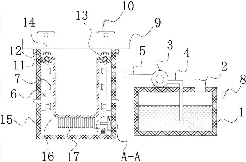
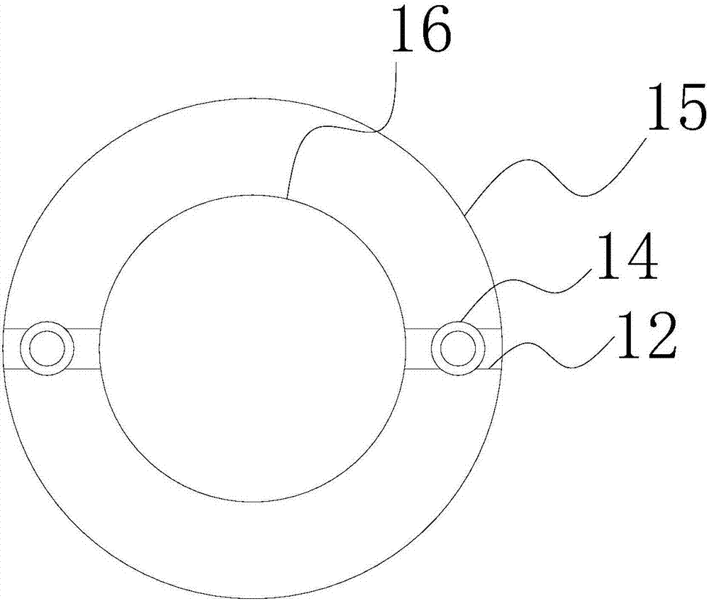
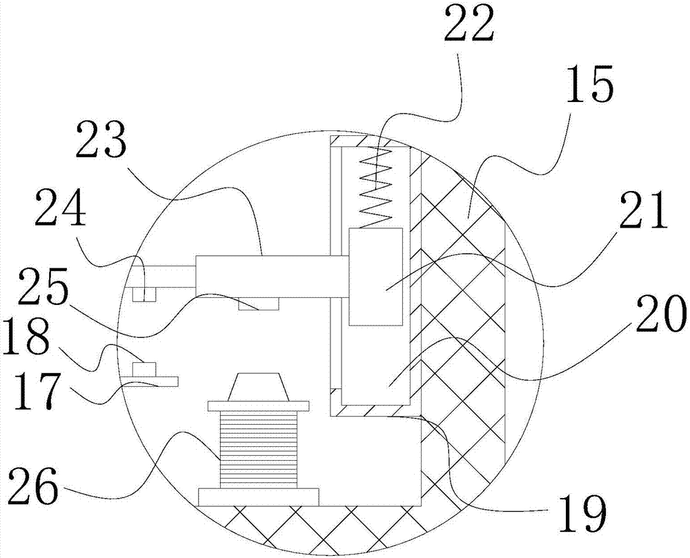
The invention discloses an industrial furnace hearth cooling device, which comprises a tank body, an inner tank is arranged inside the tank body, a cooling box is arranged on the right side of the tank body, and the top of the right side of the cooling box is connected with an inlet The liquid pipe, the top of the cooling tank and the left side of the liquid inlet pipe is fixedly connected with a water pump, the water inlet of the water pump is connected with the water inlet pipe, and the end of the water inlet pipe away from the water inlet of the water pump runs through the cooling box and extends to the cooling tank. Inside the box, the water outlet of the water pump is communicated with an outlet pipe. The present invention achieves the effect of storing the cooling liquid through the setting of the cooling box, and achieves the effect of transporting the cooling liquid through the setting of the water pump, and achieves the effect of transporting the cooling liquid into the cooling pipe through the setting of the water outlet pipe. The effect of spraying to cool the surface of the inner tank is solved, and at the same time, it solves the problem that the furnace cannot be cooled quickly and the work efficiency is reduced.

Description

technical field [0001] The invention relates to the technical field of industrial furnaces, in particular to an industrial furnace hearth cooling device. Background technique [0002] In the process of heat treatment of metal strips, due to different heat treatment purposes and process conditions, the temperature requirements for heat treatment are different, such as 900 ° C, 600 ° C, 450 ° C, etc. When the heat treatment furnace needs to rapidly cool down at high temperature, the existing Most of the technology is to open the furnace door and use the method of natural cooling to cool the inside of the furnace. This method has a slow cooling speed and cannot meet the needs of existing high production efficiency. No.: 201320727667.2), this patent greatly shortens the cooling time of the industrial furnace, improves the production efficiency of the industrial furnace, and has a simple structure and low cost by double cooling the metal strip through the circulating water pool a...

Claims


Application Information

Patent Timeline
IPC IPC(8): F27D9/00C21D9/54
CPCF27D9/00C21D9/54F27D2009/001
Inventor 沈润良
Owner CHANGXING CAZENOVE FUNANCE IND CO LTD
Why Eureka
Try Eureka