Electric push bolt type escape door lock

An electric push and escape door technology, applied in the field of escape door locks, can solve the problems of low cost performance and market promotion value, door locks cannot be opened and closed normally, and affect the rapid escape of personnel, etc., and achieves high cost performance and market promotion value. Maintenance and care, low lubrication requirements

Pending Publication Date: 2020-07-31
金捍安全(广州)智能科技有限公司
View PDF8 Cites 1 Cited by
  • Summary
  • Abstract
  • Description
  • Claims
  • Application Information

AI Technical Summary

Problems solved by technology

[0004] The above-mentioned electric push bolt type escape door lock adopts a connecting rod to drive between the motor and the dead bolt. The stability of this transmission mode is poor. During lubrication and maintenance, the connection position is likely to be stuck, resulting in the door lock not being able to open and close normally, and the failure rate is high
Especially the escape door lock is used to control the opening and closing of the fire exit escape door, this instability may affect the rapid escape of personnel in emergency situations
Moreover, the transmission method of connecting rod transmission is adopted, and the process of production and assembly is relatively complicated and time-consuming, resulting in increased production costs, low cost performance and market promotion value

Method used


Image

  • Electric push bolt type escape door lock
  • Electric push bolt type escape door lock
  • Electric push bolt type escape door lock

Examples


Embodiment Construction

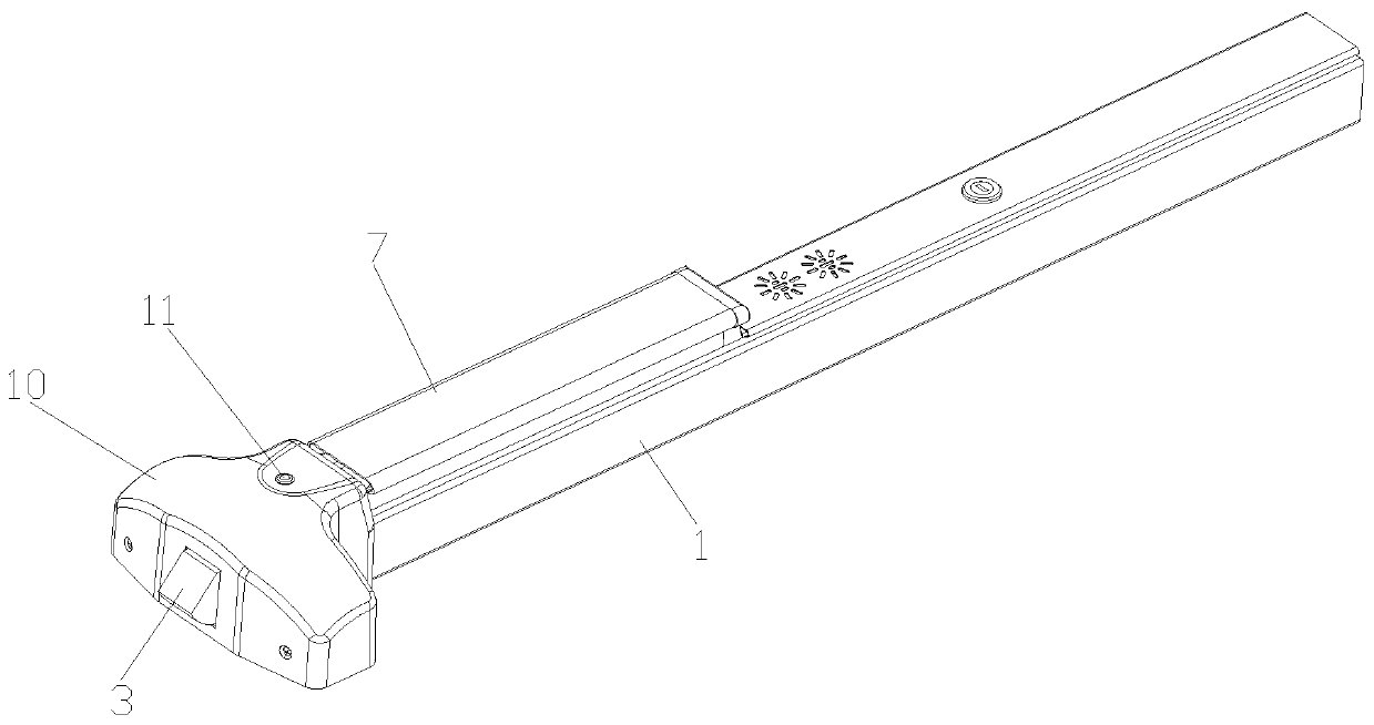
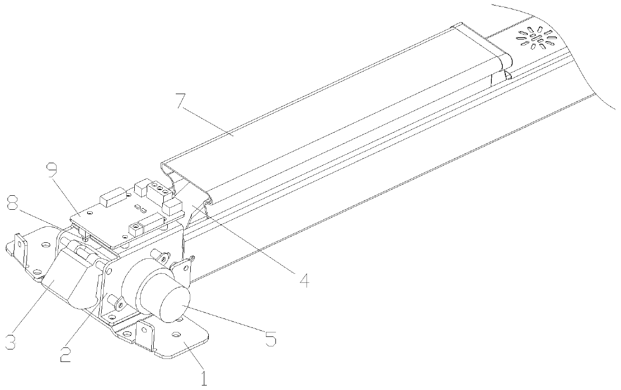
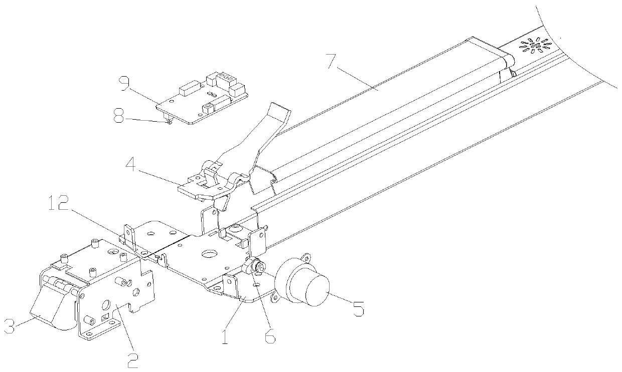
[0049] Such as Figure 1-Figure 7 As shown, an electric push bolt type escape door lock according to the present invention includes a base 1 and a mounting frame 2 arranged on the base 1, a dead bolt 3, a transmission plate 4, a motor 5, a cam 6, a push bolt 7 and Elastic parts (not shown in the figure). The base 1 is roughly in the shape of a "T", and its front end extends to both sides to form a mounting portion for mounting the bolt 3 and other components. The mounting frame 2 is a rectangular frame consisting of a top plate and two side plates. The two side plates are arranged relatively parallel on both sides of the top plate. At the same time, the bottom of the side plates extends to both sides to form a bottom edge, and the bottom edge is installed on the base 1 through bolts. , and then install the mounting frame 2 on the base 1. The deadbolt 3 is installed in the mounting frame 2, specifically, between two side plates and below the top plate. see Figure 6 , The u...


PUM


Abstract

The invention discloses an electric push bolt type escape door lock, and relates to the technical field of escape door locks. The door lock comprises a base, and a mounting frame, a bolt, a transmission plate, a motor, a cam, a push bolt and an elastic piece which are arranged on the base, wherein the bolt is arranged in the mounting frame, the upper part of the bolt is a shifting part, the middlelower part is a locking part, the shifting part is rotatably connected with the mounting frame, the middle part of the transmission plate is rotatably connected with the mounting frame, one end of the transmission plate is a connecting end, the other end of the transmission plate is a shifting end, the shifting end is positioned below the shifting part and is in contact with the shifting part, the push bolt is in sliding connection with the base, the connecting end is connected with the push bolt, the cam is arranged under the shifting end and is in contact with the shifting end, an output shaft of the motor is connected with the cam, one end of the elastic piece is connected with the bolt, and the other end of the elastic piece is connected with the mounting frame. According to the doorlock, cam contact is adopted for transmission, and the transmission parts are not needed to be connected, so that the failure rate is low, the stability and reliability are high, the maintenance and upkeep are easier, the structure is simple, the assembly is easier and the production cost is low.

Description

technical field [0001] The invention relates to the technical field of escape door locks, in particular to an electric push-bolt type escape door lock. Background technique [0002] The escape door lock is usually installed at the escape door of the fire exit, which can be quickly opened to escape in an emergency, and has a security function in normal times. Escape door locks are mainly used in shopping malls, hospitals, schools and other public places with a large flow of people. [0003] The push-bolt escape door lock is a kind of escape door lock. The push-bolt escape door lock is usually composed of a base, a push bolt, a transmission plate, a deadbolt and an elastic member. The escape door lock is installed on one side of the escape door, and the other side of the escape door is equipped with a buckle matching the deadbolt. Under the action of the elastic member, the lock tongue is exposed to the escape door on the other side, and extends into the lock buckle, so that...

Claims


Application Information

Patent Timeline
Patent Type & Authority Applications(China)
IPC IPC(8): E05B47/00E05B17/10E05B45/06E05B17/00E05B15/00E05B15/10E05B65/10
CPCE05B47/0012E05B47/023E05B17/10E05B45/061E05B17/00E05B15/00E05B15/10E05B65/1033
Inventor 何金沿
Owner 金捍安全(广州)智能科技有限公司
Why Eureka
Try Eureka