Transformer preparation system

A technology for preparing a system and a transformer, applied in the field of transformers, can solve the problems of only continuous feeding, unfavorable assembly of the assembling machine, inability to carry out fixed distance and interval feeding, etc., and achieves the effect of reasonable structure and good use effect.

Pending Publication Date: 2020-07-31
沅江市金莫特电子有限公司
View PDF0 Cites 2 Cited by
  • Summary
  • Abstract
  • Description
  • Claims
  • Application Information

AI Technical Summary

Problems solved by technology

[0002] The traditional transformer core production is divided into several separate steps. The disadvantages are: First, after the previous process is completed, it enters the material control tube, and through the material control tube, it enters the next process for processing. The bottom of the existing material control tube is open. An area larger than the height of the transformer core is reserved between the bottom of the opening and the surface of the conveyor belt in the next process, so that the transformer cores are driven one by one by the conveyor belt in the next process. In this way, when the transformer core is taken out by the conveyor belt , there will be friction between the top of the bottom transformer core and the bottom of the penultimate transformer core; second, this method can only feed materials continuously, and cannot feed materials at fixed distances and intervals, which is not conducive to the assembly of the assembly machine; 3. After assembly, it needs to be placed in the transfer box, and then sent to the detector for testing through the transfer box, and then manually placed on the corresponding conveyor to send it out

Method used


Image

  • Transformer preparation system
  • Transformer preparation system
  • Transformer preparation system

Examples


Embodiment Construction

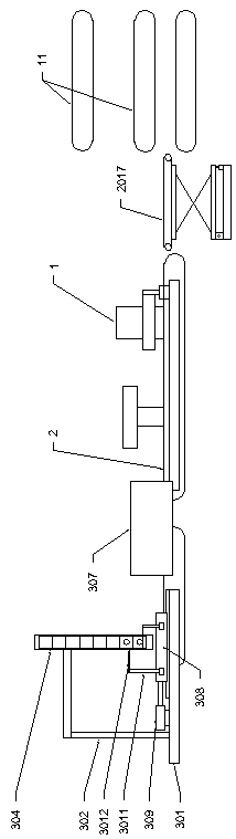
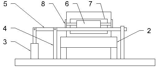
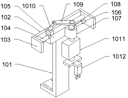
[0017] Below in conjunction with all accompanying drawings the present invention will be further described, and preferred embodiment of the present invention is: see appended figure 1 to attach Figure 7 , a kind of transformer preparation system described in the present embodiment comprises feeding frame 301, assembly machine 307, feeding belt 305, and the top end of feeding frame 301 is equipped with material storage bracket 302, and the top of material storage bracket 302 is equipped with material control pipe 304, a feeder belt 305 is installed on the feeder frame 301 below the material control pipe 304, a material control assembly is installed on the feeder frame 301 on one side of the feeder belt 305, and the assembly machine 307 is installed on the feeder in the output direction of the control assembly On the frame 301, a steering assembly is installed at the output end of the assembly machine 307, a detection frame is installed at the output end of the steering assembl...


PUM


Abstract

The invention provides a transformer preparation system. The transformer preparation system comprises a feeding rack, an assembling machine and a feeding belt. A storage bracket is mounted at one endof the top of the feeding rack, a control pipe is mounted at the top of the storage bracket, a feeding belt is mounted on the feeding rack below the material control pipe, a material control assemblyis mounted on the feeding rack on one side of the feeding belt, the assembling machine is installed on the feeding rack in the output direction of the material control assembly, a steering assembly isinstalled at the output end of the assembling machine, a detection frame is installed at the output end of the steering assembly, a detection conveying belt is installed at the top of the detection frame, a detector is installed above the detection conveying belt through a detection supporting rod, a positioning assembly is installed on the detection frame below the detector, and a lifting sorting assembly is arranged at the output end of the detection conveying belt. After the scheme is adopted, the structure is reasonable, the use effect is good, and transformer production can form an effective and continuous production line.

Description

technical field [0001] The invention relates to the technical field of transformers, in particular to a transformer preparation system. Background technique [0002] The traditional transformer core production is divided into several separate steps. The disadvantages are: First, after the previous process is completed, it enters the material control tube, and through the material control tube, it enters the next process for processing. The bottom of the existing material control tube is open. An area larger than the height of the transformer core is reserved between the bottom of the opening and the surface of the conveyor belt in the next process, so that the transformer cores are driven one by one by the conveyor belt in the next process. In this way, when the transformer core is taken out by the conveyor belt , there will be friction between the top of the bottom transformer core and the bottom of the penultimate transformer core; second, this method can only feed materia...

Claims


Application Information

Patent Timeline
Patent Type & Authority Applications(China)
IPC IPC(8): H01F41/02
CPCH01F41/0206
Inventor 夏少华肖敬芝
Owner 沅江市金莫特电子有限公司
Why Eureka
Try Eureka