
Base section with release lever

A release lever and component technology, applied in the field of base components with a release lever, can solve problems such as time-consuming, release lever drop, shape wear, etc., and achieve the effect of improving finger slippage

Pending Publication Date: 2020-07-31
GIRA GIERSIEPEN
View PDF8 Cites 0 Cited by
  • Summary
  • Abstract
  • Description
  • Claims
  • Application Information

AI Technical Summary

Problems solved by technology

However, it is time-consuming to pull out the guide element as an additional step during demolding of the cast part
In addition, due to the movement of the guide element the shape wears out more quickly and thus has a lower service life
[0004] In addition, when pulled out, the release lever connected to the base via the film hinge is overextended, so that the film hinge breaks and the release lever falls, which is disadvantageous

Method used


Image

  • Base section with release lever
  • Base section with release lever
  • Base section with release lever

Examples


Embodiment approach

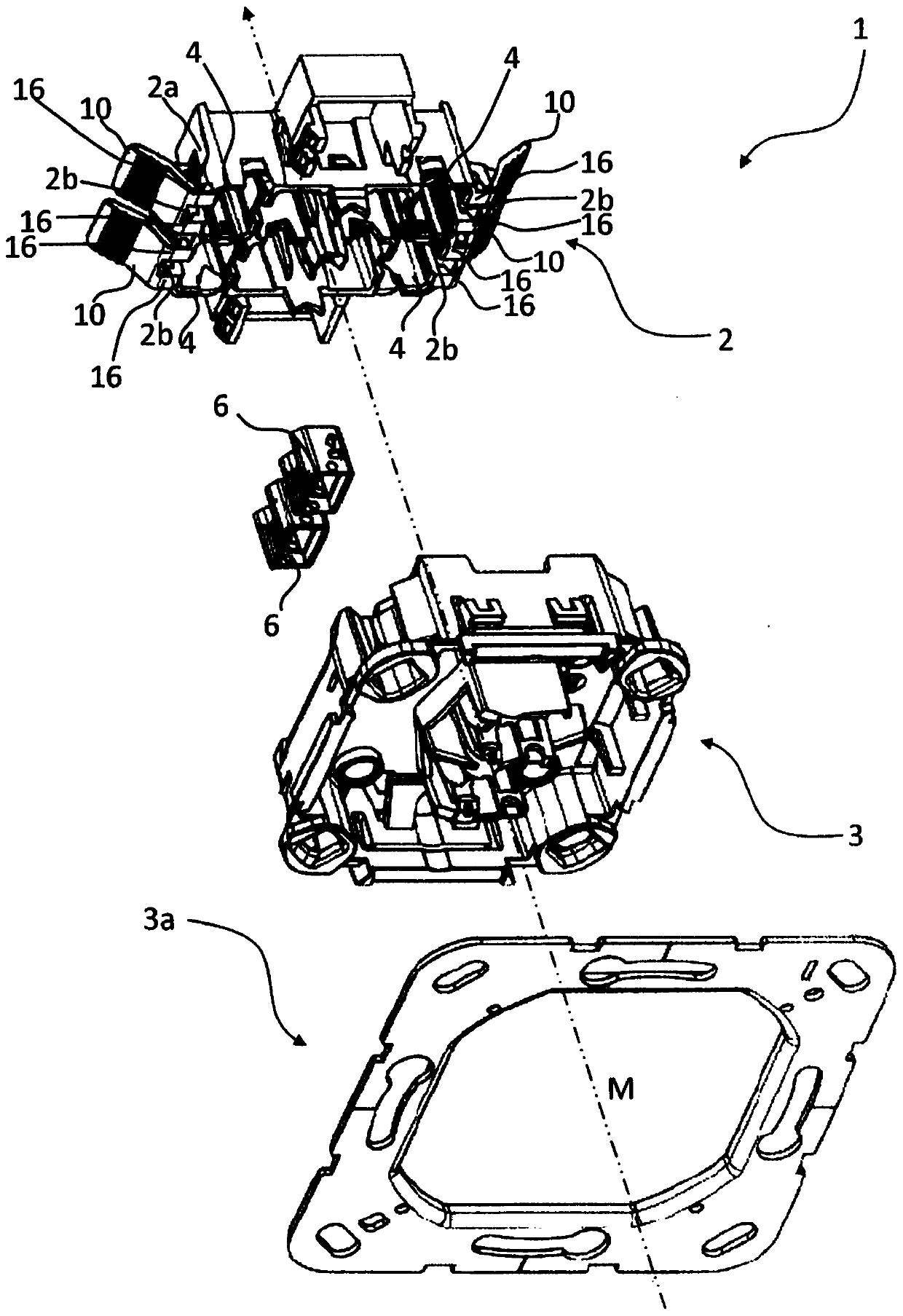
[0031] figure 1 One embodiment of an electrical installation device 1 according to the invention for fitting into a fitting opening is shown, for example a switch or a key. The electronic installation device 1 has a base part 2 which is preferably joined to a base upper part 3 to form a base. This makes it possible in particular to fix the joined base on the support ring 3a. The base upper part 3 has in particular an embossed part The embossment is designed for receiving an operating element (not shown), so that the electronic installation device 1 is especially suitable as a switch or key.

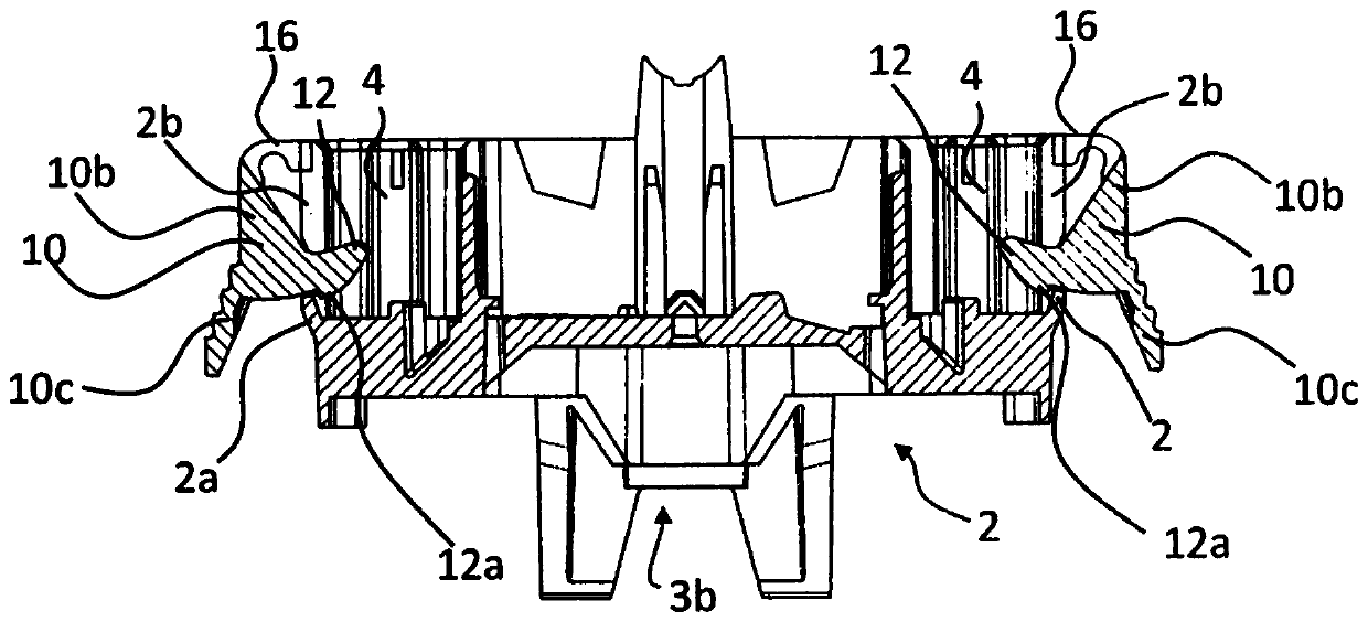
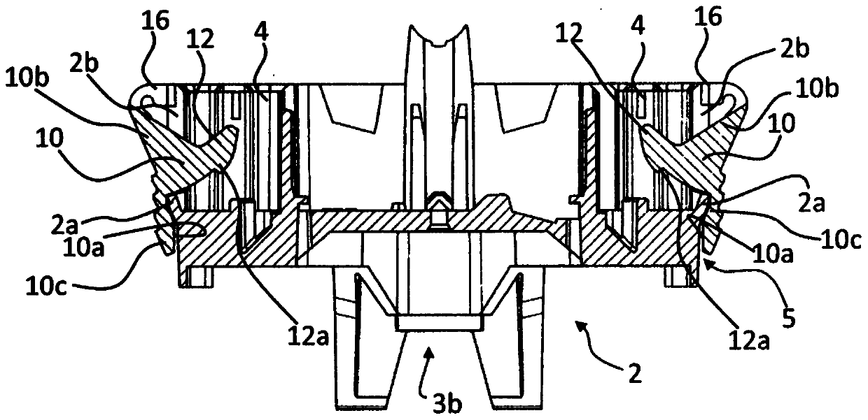
[0032] exist figure 1 The embodiment of the electronic installation device 1 shown in is held in the assembly position inserted into the assembly opening, in particular by means of screws. especially in Figure 4 to Figure 6 The alternative shown in is advantageously held in the assembly opening by means of a jaw bracket. In particular, the claw holder has at least one rotatable cl...


PUM


Abstract

An electronic mounting device is disclosed having a base member with a receptacle in which a contact housing is disposed. The contact housing has a clamping spring, and the rotatable release lever isarranged outside the outer wall of the base part, which extends parallel to the assembly direction in the region of the receptacle. In the base position of the release lever, the electrical conductorintroduced into the contact housing is secured with a clamping spring of the contact housing, and in the release lever release position, the clamping spring is actuated and the electrical conductor isreleased. The release lever has a pin on a lower side of an outer wall facing the base part, a recess is provided in the outer wall in the region of the pin, and the pin, the recess, the contact housing and the clamping spring are arranged such that in a release position of the release lever the pin operates the clamping spring of the contact housing through the recess to release the electrical conductor. The pin has an engaging projection which, in the base position, is located within the base part without the introduction of an electrical conductor and, in the region of the recess, is operatively connected in an engaging manner to a portion of the outer wall edge, preventing the engaging projection from coming out of the base part.

Description

technical field [0001] The invention relates to an electronic installation device, such as a switch or a pushbutton, for assembly in an assembly opening in an assembly direction, the electronic installation device having a base part with at least one receptacle in which a contact housing is arranged part, wherein the contact housing has a clamping spring for clamping at least one electrical conductor, wherein the rotatable (schwenkbar) release lever is arranged outside the outer wall of the base part in the region of the receptacle extends parallel to the assembly direction, wherein in the base position of the release lever, the electrical conductor introduced into the contact housing is secured by the clamping spring of the contact housing, wherein the clamping spring is actuated in the release position of the release lever and releases the conductor body, wherein the release lever has a pin on the underside facing the outside of the base part, wherein a recess is provided in...

Claims


Application Information

Patent Timeline
Patent Type & Authority Applications(China)
IPC IPC(8): H01H9/02H01H9/06
CPCH01H9/02H01H9/06H01R4/4821H01R4/483H01H1/5844H02G3/121H02G3/14
Inventor 延斯·卡林克
Owner GIRA GIERSIEPEN
Learn More