
Upper driving type no-clean vacuum fryer

A vacuum fryer, no-clean technology, is applied to the utensils for frying things in oil, household utensils, applications, etc., and can solve the problems of laboriousness, easy accumulation of residues at the bottom of the pot body, and complex structure of the bottom of the pot body, etc. The effect of simplifying the connection structure and the internal structure of the pot body, improving the frying effect and product quality, and solving the problem of residue retention and accumulation

Pending Publication Date: 2020-08-04
张培森
View PDF9 Cites 1 Cited by
  • Summary
  • Abstract
  • Description
  • Claims
  • Application Information

AI Technical Summary

Problems solved by technology

[0002] At present, the existing vacuum fryers usually have the following disadvantages: 1. Since the food will produce a lot of residues during the frying process, the residues are easy to accumulate at the bottom of the pot body, which in turn leads to the accumulation of residues in the pot body. The oil quality turns black and the acid value rises. In severe cases, the residue will surround the heating pipe in the pot, so that the heating pipe cannot dissipate heat; 2. It can only be cleaned manually every day, resulting in time-consuming, labor-intensive and laborious. Secondly, People entering the pot will also cause the pot to be contaminated with bacteria; 3. The bottom of the pot has a complex structure, many parts, and large residue discharge resistance, resulting in easy accumulation and retention of residues; 4. Most of the frying baskets are discharged by semi-automatic manual discharge. labor-intensive, time-consuming, labor-intensive

Method used


Image

  • Upper driving type no-clean vacuum fryer
  • Upper driving type no-clean vacuum fryer

Examples


Embodiment Construction

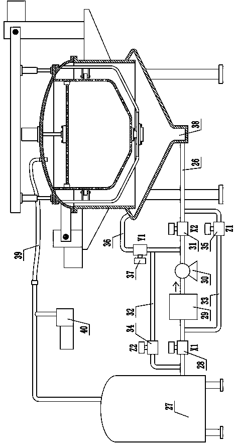
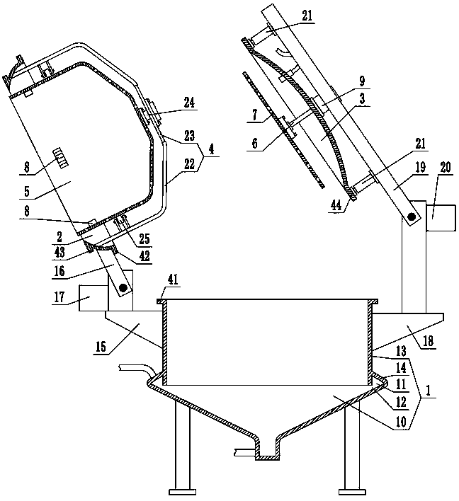
[0022] In order to describe the structure of the present invention conveniently, define now figure 1 The left side is the left side of the present invention, and the definition figure 1 The upper side is the top of the present invention.

[0023] Referring to the accompanying drawings, the upper-driven no-cleaning vacuum fryer includes a pot body 1 with a pot mouth on the top, a ring-shaped pot cover 2 sealed and pressed on the top of the pot body 1, and an opening on the ring-shaped pot cover 2 sealed and pressed. The circular pot cover 3; wherein, the ring-shaped pot cover 2 is roughly in the shape of a cone with a small diameter at the upper end and a large diameter at the lower end. Of course, the ring-shaped pot cover can also be cylindrical. Secondly, in order to improve the pot Body 1, annular pot cover 2 and circular pot cover 3 contact area and tightness, preferably the upper end of pot body 1 is annularly welded with radially outwardly protruding lower flange 41, an...


PUM


Abstract

The invention discloses an upper driving type no-clean vacuum fryer comprising a pot body, an annular pot cover pressed on the top of the pot body in a sealed mode, and a circular pot cover pressed onan opening of the annular pot cover in a sealed mode. A bracket extending into the pot body is connected to the inner wall of the annular pot cover, a frying basket with an opening in the top and located in the pot body is rotatably connected to the bracket, and a left driving mechanism capable of driving the annular pot cover to swing leftwards and upwards so as to swing the frying basket out ofthe outer side of the pot body is arranged on the outer side of the pot body; a pressing disc for driving the frying basket to rotate is mounted at the bottom of the circular pot cover; a right driving mechanism for driving the circular pot cover to lift up and down and swing towards the upper right side is arranged at the outer side part of the pot body. The vacuum fryer is simple in structure,the problems of residue retention and accumulation are solved, the residue discharging effect is improved, vacuum frying operation can be achieved, frying work and pan bottom self-cleaning work can beachieved at the same time, the cleanliness of oil in the frying process can be guaranteed, and the frying effect and the product quality are improved.

Description

technical field [0001] The invention relates to an upper-driven no-cleaning vacuum fryer. Background technique [0002] At present, the existing vacuum fryers usually have the following disadvantages: 1. Since the food will produce a lot of residues during the frying process, the residues are easy to accumulate at the bottom of the pot body, which in turn leads to the accumulation of residues in the pot body. The oil quality turns black and the acid value rises. In severe cases, the residue will surround the heating pipe in the pot, so that the heating pipe cannot dissipate heat; 2. It can only be cleaned manually every day, resulting in time-consuming, labor-intensive and laborious. Secondly, People entering the pot will also cause the pot to be contaminated with bacteria; 3. The bottom of the pot has a complex structure, many parts, and large residue discharge resistance, resulting in easy accumulation and retention of residues; 4. Most of the frying baskets are discharged...

Claims


Application Information

Patent Timeline
Patent Type & Authority Applications(China)
IPC IPC(8): A47J37/12
CPCA47J37/12A47J37/1271A47J37/1276
Inventor 张培森
Owner 张培森
Learn More