
An adjustable escape device and its control method

An escape device and adjustable technology, applied in the field of escape devices, can solve the problems of incompatibility with the elderly and children, low transportation efficiency, impact force of trapped people, etc., and achieve the effect of widening the scope of applicable people, ensuring personal safety, and running fast.

Active Publication Date: 2021-04-13
JIANGSU UNIV OF TECH
View PDF14 Cites 0 Cited by
  • Summary
  • Abstract
  • Description
  • Claims
  • Application Information

AI Technical Summary

Problems solved by technology

The existing technologies of these two devices are affected by external environmental factors and cannot meet the requirements of a fast, stable and safe escape process under any state.
For example, patent 2017113850648 discloses a high-altitude escape device. The device requires a certain reserved space around the building, and the trapped people descend from high altitude to the ground through the conveyor belt. However, this device is not suitable for buildings with high floors. Low efficiency, vulnerable to weather, and easy to collide with each other during use
In addition, the use of the device also requires the trapped personnel to have high psychological quality and operational skills, so as not to be able to better control the descent speed.
Patent No. 2017111303459 discloses a mechanical escape device, which completely relies on gravity to descend and requires professional training for the user to operate proficiently. It is not suitable for the elderly and children, and it is easy to cause a certain impact on the trapped persons due to the rapid descent.
It can be seen that none of the existing escape devices can meet the needs of fast, simple and safe escape at the same time.

Method used


Image

  • An adjustable escape device and its control method
  • An adjustable escape device and its control method
  • An adjustable escape device and its control method

Examples


Embodiment

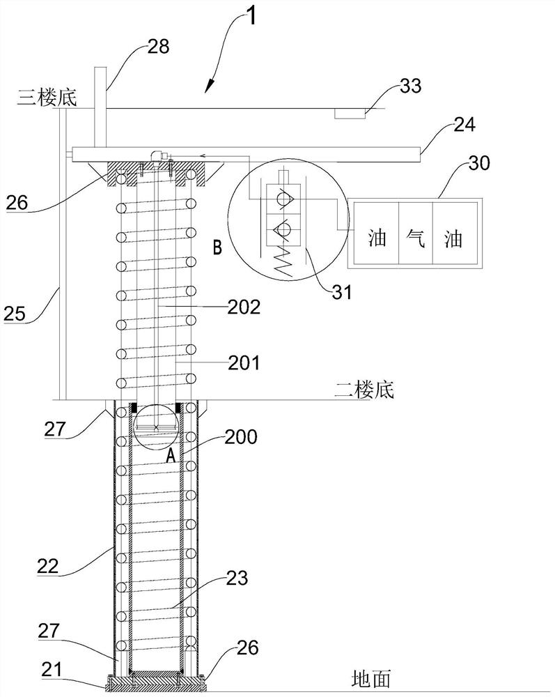
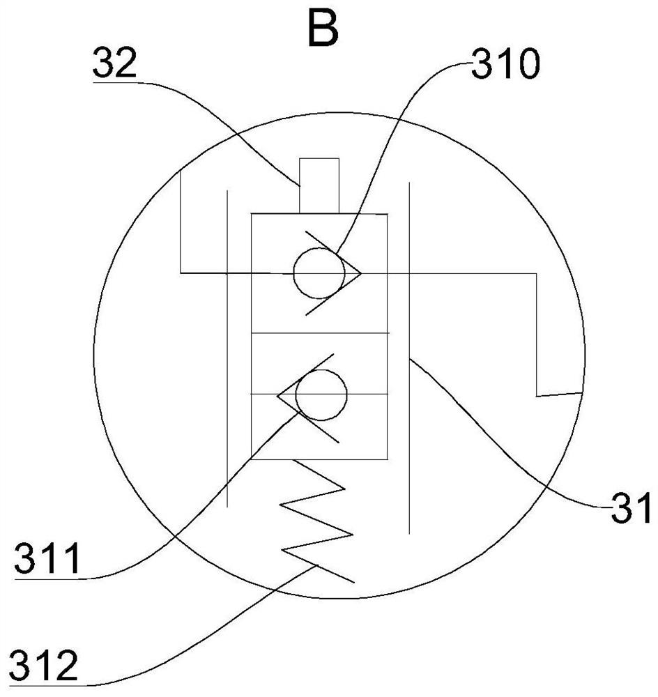
[0032] Such as figure 1 As shown, this embodiment provides an adjustable escape device 1 for trapped persons to escape from the third floor to the second floor, including a lifting mechanism and a control mechanism, the control mechanism is used to adjust the descending speed of the lifting mechanism.

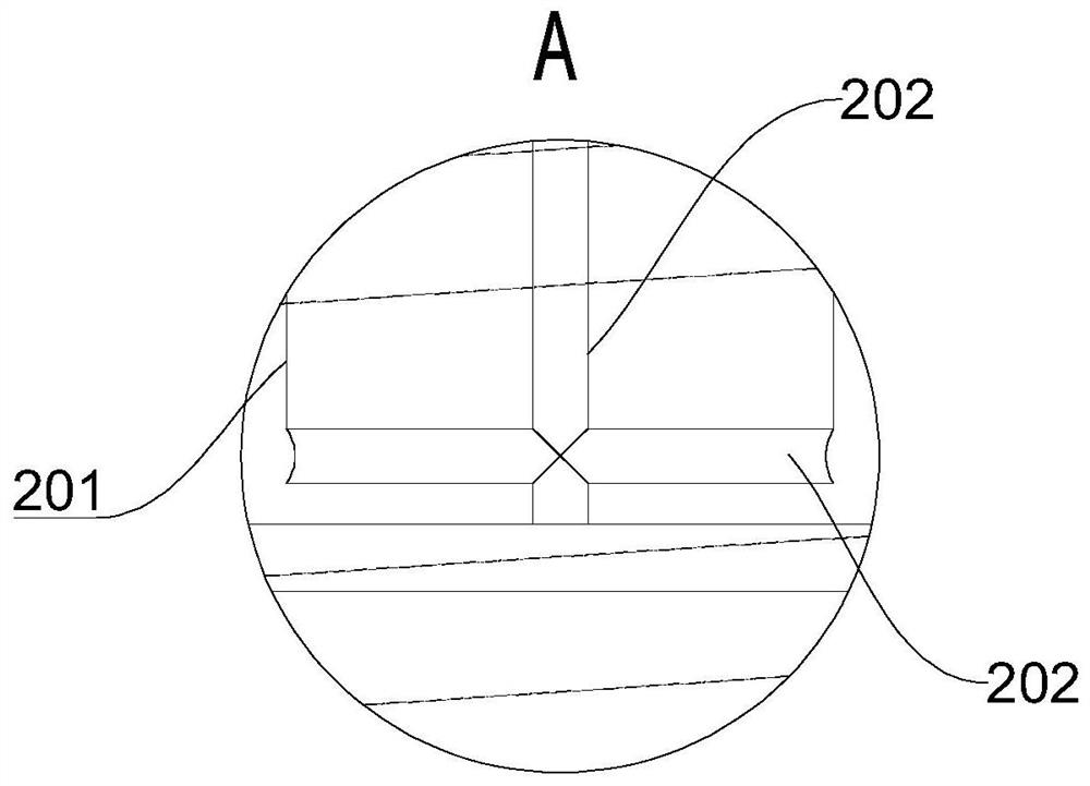
[0033] The above-mentioned lifting mechanism includes a hydraulic cylinder 20, a mounting plate 21, a guide pipe 22, a compression spring 23, a lifting platform 24 and a guide rail 25. The above-mentioned hydraulic cylinder 20 is fixedly connected to the ground through the above-mentioned mounting plate 21, and the above-mentioned guide pipe 22 is sleeved on the above-mentioned hydraulic pressure. Outside the cylinder body 200 of the cylinder 20, the above-mentioned compression spring 23 is sleeved on the above-mentioned hydraulic cylinder 20 and arranged in the above-mentioned guide tube 22, the above-mentioned lifting platform 24 is fixedly connected with the free end of the p...


PUM


Abstract

The invention belongs to the technical field of escape devices, and in particular relates to an adjustable escape device and a control method thereof, including a lifting mechanism and a control mechanism, and the control mechanism is used to adjust the descending speed of the lifting mechanism. The lifting mechanism includes a hydraulic cylinder, a mounting plate, a guide tube, a compression spring, a lifting platform and a guide rail. The hydraulic cylinder is connected to the ground through the mounting plate, the guide tube is set outside the cylinder body of the hydraulic cylinder, and the compression spring is set on the hydraulic cylinder. The lifting platform is connected with the piston rod of the hydraulic cylinder and can slide up and down along the guide rail. The control mechanism includes a governor, a reversing valve, a controller and an electromagnet. The governor is installed on the lifting platform, the reversing valve is installed on the governor, the controller is installed on the reversing valve, and the electromagnet is installed on the On the top wall of the building, it is used to absorb and fix the lifting platform. The adjustable escape device provided by the invention is easy to use, fast and safe.

Description

technical field [0001] The invention belongs to the technical field of escape devices, and in particular relates to an adjustable escape device and a control method thereof. Background technique [0002] At present, the main escape devices of high-rise buildings can be divided into two types. One is to send the trapped people away from the fire scene along the wall outside the window through the retraction and release of ropes, and the other is to install mechanical escape devices inside the high-rise Evacuate the trapped persons from the danger zone. The existing technologies of these two devices are affected by external environmental factors and cannot meet the requirements of fast, stable and safe escape process under any state. For example, patent 2017113850648 discloses a high-altitude escape device. The device requires a certain reserved space around the building, and the trapped people descend from high altitude to the ground through the conveyor belt. However, this ...

Claims


Application Information

Patent Timeline
Patent Type & Authority Patents(China)
IPC IPC(8): A62B1/02A62B1/04
CPCA62B1/02A62B1/04
Inventor 陈宇俞成涛王洪昌代巧刘凯磊
Owner JIANGSU UNIV OF TECH
Learn More