Assistant machining clamping device for bearing inner rings

A technology of auxiliary processing and clamping device, used in positioning devices, metal processing equipment, metal processing mechanical parts, etc., can solve the problems of insufficient processing accuracy of bearing inner ring, affecting the efficiency of processing bearing inner ring, bearing inner ring falling off, etc.

Inactive Publication Date: 2020-08-04
NORTHWEST A & F UNIV
View PDF0 Cites 2 Cited by
  • Summary
  • Abstract
  • Description
  • Claims
  • Application Information

AI Technical Summary

Problems solved by technology

[0002] When machining the inner ring of the bearing, the inner ring of the bearing is easy to fall off from the fixing device, so the machining accuracy of the inner ring of the bearing will be insufficient, and the efficiency of machining the inner ring of the bearing will be affected

Method used


Image

  • Assistant machining clamping device for bearing inner rings

Examples


Embodiment Construction

[0006] This patent is discussed below according to the examples in the accompanying drawings of this patent.

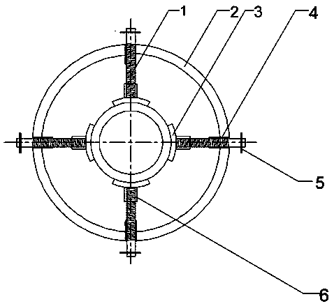
[0007] Referring to the accompanying drawings, this patent has a ring-shaped support frame (2), and four through holes are evenly distributed on the ring-shaped support frame (2), and a track (4) is welded on the through hole, and the track (4) has The screw thread that can fully cooperate with the lead screw (1), the length of the track (4) is greater than the depth of the through hole of the circular support frame (2) but less than 1 / 2 of the length of the lead screw (1). There is a rotating handle (5) on the lead screw (1), and the inside of the connection block (6) has a deep hole whose depth does not exceed three-quarters of the depth of the connection block (6), and there is a hole inside that matches the lead screw (1). The threads, the connecting block (6) and the buffer pad (3) are fixedly connected by glue. When clamping the inner ring of the bearing, place...


PUM


Abstract

The invention discloses an assistant machining clamping device for bearing inner rings. The assistant machining clamping device for the bearing inner rings comprises lead screws, an annular supportingframe, cushion pads, tracks, rotating handles and connecting blocks, and can be used for controllably clamping the bearing inner rings in different sizes to machine the inner rings. The assistant machining clamping device for the bearing inner rings has the advantages of being simple in structure and easy to operate, can reduce damage to the bearing inner rings in the clamping process, and can clamp the bearing inner rings more stably to facilitate machining of the bearing inner rings.

Description

technical field [0001] The patent relates to a clamp, in particular to a clamping device for auxiliary processing of a bearing inner ring. Background technique [0002] When machining the inner ring of the bearing, the inner ring of the bearing is easy to fall off from the fixing device, so the machining accuracy of the inner ring of the bearing will be insufficient, and the efficiency of machining the inner ring of the bearing will be affected. Contents of the invention [0003] The technical scheme of a clamping device for auxiliary processing of the inner ring of a bearing disclosed in this patent is: four through holes are evenly distributed on a circular support frame, and a threaded track is welded inside the through hole, and the thread and the lead screw The threads are matched, and the length of the track is greater than the depth of the through hole of the circular support frame but less than half of the length of the screw. By rotating the handle, the screw move...

Claims


Application Information

Patent Timeline
Patent Type & Authority Applications(China)
IPC IPC(8): B23Q3/00
CPCB23Q3/00
Inventor 胡耀华王绍襄熊杰
Owner NORTHWEST A & F UNIV
Why Eureka
Try Eureka