A clamping structure for a core drilling machine

A clamping structure, core drilling rig technology, applied in drill pipe, drill pipe, drilling equipment and other directions, can solve the problems of unreliable clamping and positioning, unstable structure, drill pipe wear, etc., to ensure service life and timely operation , damage reduction effect

Inactive Publication Date: 2016-08-03
CHANGSHA EXPLORATION MACHINERY FACTORY
View PDF4 Cites 0 Cited by
  • Summary
  • Abstract
  • Description
  • Claims
  • Application Information

AI Technical Summary

Problems solved by technology

[0004] The purpose of the present invention is to provide a clamping structure for a core drilling machine to solve the technical problems of unreliable clamping and positioning, slipping, and collapse of the drill pipe due to wear and scratches on the drill pipe, resulting in structural instability

Method used


Image

  • A clamping structure for a core drilling machine
  • A clamping structure for a core drilling machine
  • A clamping structure for a core drilling machine

Examples


Embodiment Construction

[0026] The embodiments of the present invention will be described in detail below with reference to the accompanying drawings, but the present invention can be implemented in many different ways defined and covered by the claims.

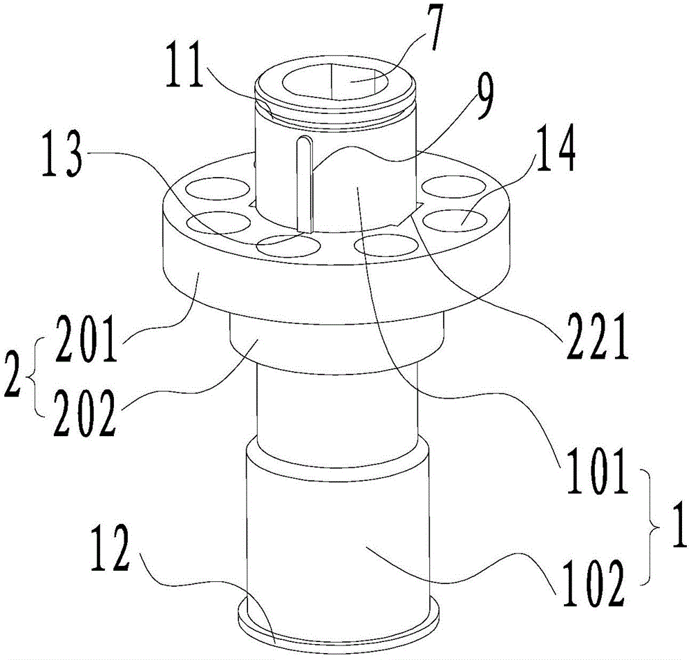
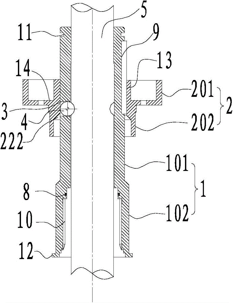
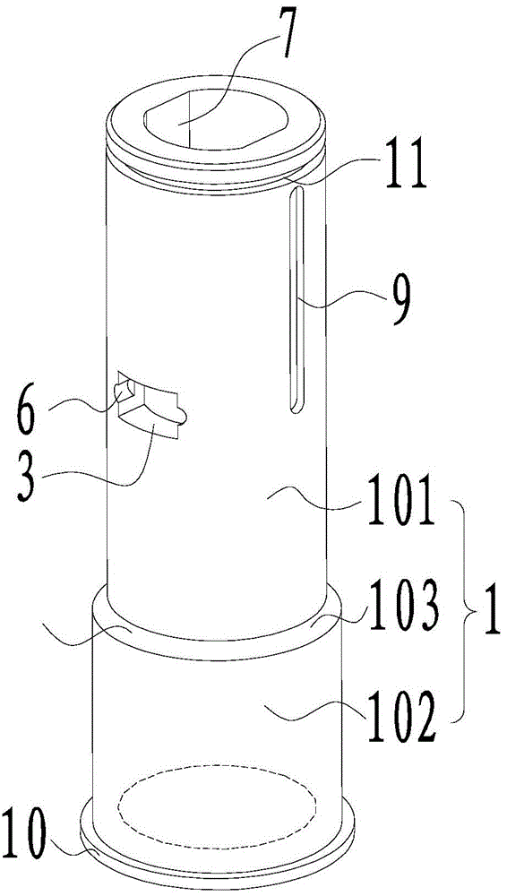
[0027] figure 1 It is a three-dimensional structural schematic diagram of a clamping structure for a core drilling machine in a preferred embodiment of the present invention; figure 2 It is a schematic cross-sectional structure diagram of a clamping structure for a core drilling machine in a preferred embodiment of the present invention; image 3 is a schematic structural view of a guide sleeve in a preferred embodiment of the present invention; Figure 4 It is a structural schematic diagram of the collar of the preferred embodiment of the present invention.

[0028] Such as figure 1 and figure 2 As shown, the clamping structure for the core drilling rig of the present embodiment includes a guide sleeve 1 and a ring sleeve outside the drill ro...


PUM


Abstract

A clamping structure for a core drilling rig, including a guide sleeve, the ring sleeve is outside the drill pipe of the drilling rig, used to transmit torque and ensure the straightness of the drill pipe; a collar, the ring sleeve is outside the guide sleeve and slides axially along the collar The drill pipe is clamped or released by pushing the moving parts or rolling parts; the rolling groove is opened on the guide sleeve to accommodate the moving parts or rolling parts and to position the moving parts or rolling parts, and the moving parts or The rolling part enters to clamp the drill pipe in the guide sleeve or withdraws to release the clamping of the drill pipe in the guide sleeve; the moving part or rolling part is set at the rolling groove between the guide sleeve and the collar, and is moved by the moving part or The way the rolling element rolls applies a clamping force to the drill rod of the drilling rig to clamp the drill rod, or moves in the opposite direction to release the clamping of the drill rod. The clamping structure clamps and releases the clamping of the drill pipe, and the effect of clamping and releasing the clamping of the drill pipe is better, the clamping is more reliable, and the operation is more timely.

Description

technical field [0001] The invention relates to the technical field of engineering drilling equipment, in particular to a clamping structure for a core drilling machine. Background technique [0002] The core drilling rig has the characteristics of modular design, easy disassembly and assembly, high drilling efficiency, convenient transportation, low cost, and environmental protection. It can drill into strata with a depth of less than 350m, and can be widely used in core drilling work with extremely complex ground conditions. [0003] There are many types of core drilling rigs in my country, but there are many problems in the clamping and positioning of the drill rods of the existing core drilling rigs. The clamping and positioning of the drill rods are generally in the form of clamping by butterfly springs and automatic centering of slips. During use, because the drill pipe is clamped by slips, the drill pipe will be worn and scratched, which will lead to a series of probl...

Claims


Application Information

Patent Timeline
Patent Type & Authority Patents(China)
IPC IPC(8): E21B19/10E21B7/04
Inventor 李武初肖燕波谭粮纲彭儒金孔中捷李忠邹煜时余海炼戴圣海邱华
Owner CHANGSHA EXPLORATION MACHINERY FACTORY
Why Eureka
Try Eureka