Clamp for machine tool

A fixture and machine tool technology, applied in the field of machinery, can solve problems such as unstable clamping of machine tools and inability to meet actual use, and achieve the effect of simple and reasonable overall structural design and meeting requirements for use

Inactive Publication Date: 2020-04-03
黄光明
View PDF0 Cites 0 Cited by
  • Summary
  • Abstract
  • Description
  • Claims
  • Application Information

AI Technical Summary

Problems solved by technology

[0002] During the use of the machine tool, the workpiece needs to be clamped, and then cut or processed. The existing machine tools are unstable in clamping and cannot meet the actual use.

Method used


Image

  • Clamp for machine tool

Examples


Embodiment 1

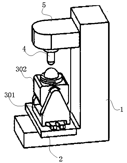
[0015] A fixture for a machine tool, comprising an L-shaped support base 1, a workbench 2, an indexing circle work unit arranged on the workbench 2, and a tool 4 adapted to the index circle work unit, and the workbench 2 is arranged on an L-shaped On the support base 1 , an extended knife rest 5 is arranged on the L-shaped support base 1 , the extended knife rest 5 is arranged above the indexing circle working unit, and the cutter 4 is fixed on the extended knife rest 5 .

Embodiment 2

[0017] The indexing circle working unit of the fixture for machine tools of the present invention comprises a pendulum angle body support 301 and an indexing circle workbench 302 arranged on the pendulum angle body support 301, and the pendulum angle body support 301 is fixedly arranged on the workbench 2, and others are related to implementation Example 1 is consistent.

Embodiment 3

[0019] The material of the L-shaped support base 1 of the fixture for machine tools of the present invention is stainless steel, and the others are consistent with Embodiment 1 or 2.


PUM


Abstract

The invention discloses a clamp for a machine tool. The clamp comprises an L-shaped supporting base (1), a workbench (2), a reference circle working unit arranged on the workbench (2) and a cutter (4)matched with the reference circle working unit; the workbench (2) is arranged on the L-shaped supporting base (1); an extension cutter rest (5) is arranged on the L-shaped supporting base (1); the extension cutter rest (5) is arranged above the reference circle working unit; and the cutter (4) is fixed to the extension cutter rest (5). The whole structural design of the clamp is simple and reasonable; all the components of the clamp are matched with one another; the use requirements of the machine tool can be met; and cutting or trimming is achieved.

Description

technical field [0001] The invention relates to the mechanical field, in particular to a fixture for machine tools. Background technique [0002] During the use of the machine tool, the workpiece needs to be clamped, and then cut or processed. The existing machine tools are unstable in clamping and cannot meet the actual use. Contents of the invention [0003] The purpose of the present invention is to overcome the problems of the prior art and provide a fixture for machine tools. [0004] A fixture for a machine tool of the present invention includes an L-shaped support base, a workbench, an indexing circle work unit on the workbench and a tool matched with the index circle work unit, and the workbench is set on an L-shaped On the support base, the L-shaped support base is provided with an extended knife holder, the extended knife holder is arranged above the indexing circle working unit, and the knife is fixed on the extended knife holder. [0005] As a further improve...

Claims


Application Information

Patent Timeline
Patent Type & Authority Applications(China)
IPC IPC(8): B23Q3/06B23Q1/25
CPCB23Q1/25B23Q3/06
Inventor 黄光明
Owner 黄光明
Why Eureka
Try Eureka