Thermostat control device and thermostat control method

A control device and thermostat technology, applied in the control of coolant flow, machine/engine, engine components, etc., can solve the problems of vehicle fuel economy deterioration, damage to the engine, and shorten the service life of the engine to achieve small fluctuations Effect

Pending Publication Date: 2020-08-04
HITACHI AUTOMOTIVE SYST SUZHOU
View PDF0 Cites 5 Cited by
  • Summary
  • Abstract
  • Description
  • Claims
  • Application Information

AI Technical Summary

Problems solved by technology

[0002] As we all know, the best working temperature of the engine is around 90°C, and too high engine water temperature will damage the engine, reduce the service life of the engine, and make the fuel economy of the vehicle worse

Method used


Image

  • Thermostat control device and thermostat control method
  • Thermostat control device and thermostat control method
  • Thermostat control device and thermostat control method

Examples


Embodiment approach 1

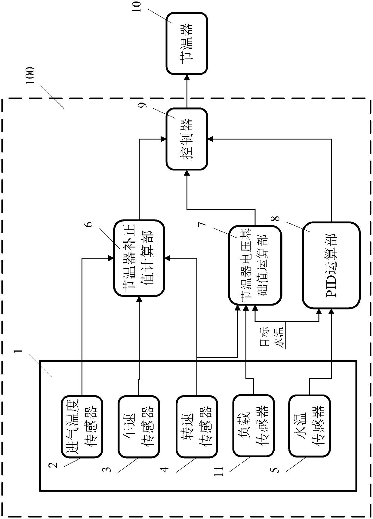
[0020] figure 1 It is a block diagram showing the thermostat control device 100 according to Embodiment 1 of the present invention. The thermostat control device 100 will be specifically described below.

[0021] The thermostat control device 100 outputs a thermostat control voltage to the thermostat 10 so that the thermostat 10 can adjust the temperature of the coolant of the engine appropriately. The thermostat control device 100 includes: a sensor group 1 , a thermostat correction value calculation unit 6 , a thermostat voltage base value calculation unit 7 , a PID calculation unit 8 , and a controller 9 .

[0022] The sensor group 1 includes a plurality of sensors: an intake air temperature sensor 2 , a vehicle speed sensor 3 , a rotational speed sensor 4 , a water temperature sensor 5 and a load sensor 11 . The intake air temperature sensor 2 detects the intake air temperature of the engine, the vehicle speed sensor 3 detects the speed of the vehicle, the rotational sp...

Embodiment approach 2

[0057] Figure 6 A block diagram showing a thermostat control device 100' according to Embodiment 2, Figure 7 The control method of the thermostat control device according to Embodiment 2 is shown, and the same blocks and steps as those in Embodiment 1 are denoted by the same reference numerals. Only the parts of Embodiment 2 that are different from Embodiment 1 will be described below.

[0058] Such as Figure 6 As shown, the thermostat control device 100' further includes a battery voltage correction value calculation unit 11. The battery voltage correction value calculation unit 11 has a battery voltage correction table T2 with the battery voltage VB as a variable, and refers to the battery voltage correction table T2 based on the battery voltage VB. The table T2 outputs the battery voltage correction value Cvb to the controller 9 . Therefore, when calculating the thermostat control voltage Vctl, the controller can take the battery voltage VB of the car into considerati...


PUM


Abstract

The invention relates to a thermostat control device and a thermostat control method. The thermostat control device comprises a sensor group, thermostat correction value calculation unit, a thermostatvoltage reference value calculation unit, a PID computation unit and a control unit, wherein the sensor group is provided with a plurality of sensors and comprises an intake air temperature sensor, avehicle speed sensor, a rotating speed sensor, a load sensor and a water temperature sensor; the thermostat correction value calculation unit is used for calculating a thermostat correction value onthe basis of the output of each of the intake air temperature sensor, the vehicle speed sensor and the rotational speed sensor correspondingly; the thermostat voltage reference value calculation unitis used for calculating a thermostat voltage reference value on the basis of the output of the rotational speed sensor and the load sensor in the sensor group and the target water temperature of cooling liquid correspondingly; the PID computation unit is used for calculating a P value, an I value and a D value through PID operation according to the current coolant water temperature output by the water temperature sensor and the target water temperature; and the control unit is used for calculating a thermostat control voltage on the basis of the thermostat correction value, the thermostat voltage reference value, the P value, the I value, and the D value correspondingly and outputting the thermostat control voltage to the thermostat.

Description

technical field [0001] The invention relates to a thermostat control device and a thermostat control method, in particular to a thermostat control device and a thermostat control method for engine water temperature control. Background technique [0002] As we all know, the optimum operating temperature of the engine is around 90°C, and too high engine water temperature will damage the engine, reduce the service life of the engine, and worsen the fuel economy of the vehicle. [0003] Usually, such as figure 2 As shown, the thermostat 4' (mostly an electronic thermostat) is used to regulate the temperature of the engine 6'. Specifically, the thermostat 4' adjusts the opening of the radiator 3 according to the temperature of the coolant. 'The amount of water, change the size of the coolant flow through the engine 6 'circulation, to ensure that the engine 4 'works in a suitable temperature range. Contents of the invention [0004] The technical problem to be solved by the in...

Claims


Application Information

Patent Timeline
Patent Type & Authority Applications(China)
IPC IPC(8): F01P7/16
CPCF01P7/167
Inventor 赵岩松陈闯
Owner HITACHI AUTOMOTIVE SYST SUZHOU
Why Eureka
Try Eureka