
Fingerprint identification method and device, electronic equipment and computer readable storage medium

A fingerprint identification and fingerprint technology, which is applied in the direction of computer parts, calculation, character and pattern recognition, etc., can solve the problems of unfavorable fingerprint identification, affecting fingerprint identification, different force, etc., and achieve the effect of improving user experience and facilitating fingerprint identification

Pending Publication Date: 2020-08-04
BEIJING XIAOMI MOBILE SOFTWARE CO LTD
View PDF3 Cites 0 Cited by
  • Summary
  • Abstract
  • Description
  • Claims
  • Application Information

AI Technical Summary

Problems solved by technology

[0003] However, in the related art, the method of setting the fingerprint recognition sensor for fingerprint recognition has great limitations, and for the determination of the user's contact area on the terminal, only the center of gravity of the contact area can be determined. A weighted average is performed. However, when the user touches the terminal, the force of each position of the finger is different, so the center of gravity determined in this way does not necessarily coincide with the center (centroid) of the contact area.
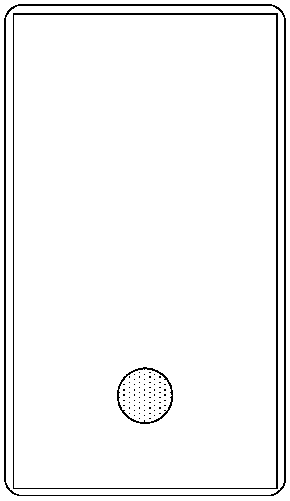
In the related art, when the center of gravity is located in the fingerprint recognition area, the center of gravity is used as the center of the circle, the circular area is determined with a fixed radius, and all the fingerprint recognition sensors in the circular area are activated for fingerprint identification. The center coincides, and the contact area in the circular area may only be a small part of the contact area between the user and the terminal, which will result in incomplete fingerprint information collected
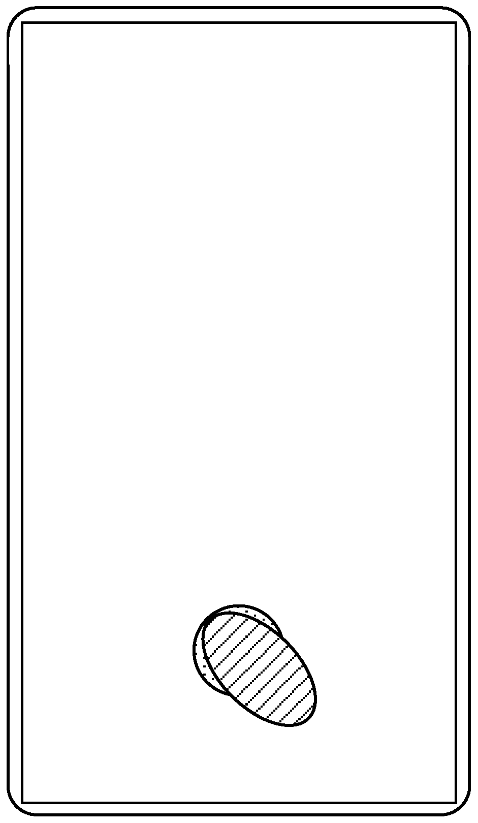
[0004] E.g figure 1 As shown, when the center of gravity of the contact area is within the fingerprint recognition area, the center of gravity will be taken as a concern, and a circular area will be determined with a fixed radius. When the user performs fingerprint recognition operations, the shape of the contact area is generally not circular, for example figure 2 As shown in , the shape of the contact area between the user's finger and the terminal is oval, so the contact area may not cover the circular area in the fingerprint recognition area, so that there is a gap between the contact area and the circular area. All fingerprint recognition sensors, such as fingerprint recognition sensors are photoelectric sensors, then in figure 2 In the case shown, since the photoelectric sensor in the gap is not blocked by the finger, the leaked light will be observed by the user, affecting the user experience, and the collected fingerprint information does not even reach half of the contact area, resulting in the collected Incomplete fingerprint information
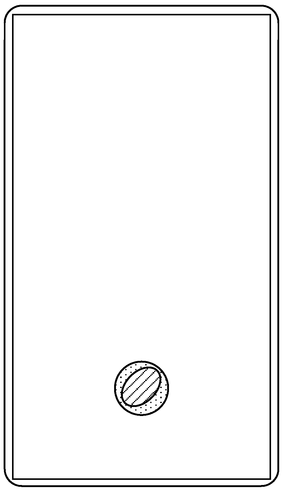
[0005] And even if the contact area is completely within the circular area, such as image 3 As shown in , since the radius of the circular area is fixed, the user can only touch part of the finger, for example, only the fingertip with the fingerprint recognition area, which still exists figure 2 The problem of light leakage pointed out, and the collected fingerprint information is very little, which is not conducive to the identification of fingerprints
[0006] If the circular area is reduced to avoid the problem of light leakage, such as Figure 4 As shown, the circular area (area shown by the dotted line) is within the contact area due to its small area, and the collected fingerprint information is too little, which seriously affects the identification of fingerprints.

Method used


Image

  • Fingerprint identification method and device, electronic equipment and computer readable storage medium
  • Fingerprint identification method and device, electronic equipment and computer readable storage medium
  • Fingerprint identification method and device, electronic equipment and computer readable storage medium

Examples


Embodiment Construction

[0079] Reference will now be made in detail to the exemplary embodiments, examples of which are illustrated in the accompanying drawings. When the following description refers to the accompanying drawings, the same numerals in different drawings refer to the same or similar elements unless otherwise indicated. The implementations described in the following exemplary examples do not represent all implementations consistent with the present disclosure. Rather, they are merely examples of apparatuses and methods consistent with aspects of the present disclosure as recited in the appended claims.

[0080] Figure 5 It is a schematic flowchart of a fingerprint identification method shown according to an embodiment of the present disclosure. The fingerprint identification method shown in this disclosure can be applied to terminals such as mobile phones, tablet computers, and wearable devices. The terminals include a touch module and a fingerprint identification module, and the tou...


PUM


Abstract

The embodiment of the invention provides a fingerprint identification method suitable for a terminal, and the method comprises the steps: obtaining a contact region parameter determined by a touch module; determining a contact pattern according to the contact area parameters; and collecting or identifying the fingerprint information in the contact pattern. According to the embodiment of the invention, a contact pattern is determined according to contact area parameters; a fingerprint identification sensor in a contact pattern can be controlled to acquire or identify fingerprint information inthe contact pattern; on one hand, a light leakage phenomenon does not occur during fingerprint identification, so that the use experience of a user is improved, and on the other hand, more fingerprintinformation can be collected, and subsequent operations such as fingerprint identification and fingerprint verification are facilitated.

Description

technical field [0001] The present disclosure relates to the field of touch technology, and in particular to a fingerprint identification method, a fingerprint identification device, electronic equipment and a computer-readable storage medium. Background technique [0002] With the development of fingerprint identification technology, in the current terminal, fingerprint identification under the screen can be realized, that is, a fingerprint identification sensor can also be set in the display area to identify fingerprints. [0003] However, in the related art, the method of setting the fingerprint recognition sensor for fingerprint recognition has great limitations, and for the determination of the user's contact area on the terminal, only the center of gravity of the contact area can be determined. A weighted average is performed. However, when the user touches the terminal, the force of each position of the finger is different, so the center of gravity determined in this ...

Claims


Application Information

Patent Timeline
Patent Type & Authority Applications(China)
IPC IPC(8): G06K9/00G06V10/141
CPCG06V40/13G06V40/1318G06V40/1306G06F3/044G06V10/235G06V10/141G06V40/1347G06V40/1365
Inventor 胡现坤
Owner BEIJING XIAOMI MOBILE SOFTWARE CO LTD
Learn More