
Aircraft engine nacelle

An engine nacelle and engine technology, applied in the direction of machines/engines, engine manufacturing, aircraft parts, etc., can solve the problem of not being able to use large-sized nacelles

Active Publication Date: 2020-08-04
SAFRAN NASEL
View PDF5 Cites 0 Cited by
  • Summary
  • Abstract
  • Description
  • Claims
  • Application Information

AI Technical Summary

Problems solved by technology

This solution cannot be used for large-sized cabins

Method used


Image

  • Aircraft engine nacelle
  • Aircraft engine nacelle
  • Aircraft engine nacelle

Examples


Embodiment Construction

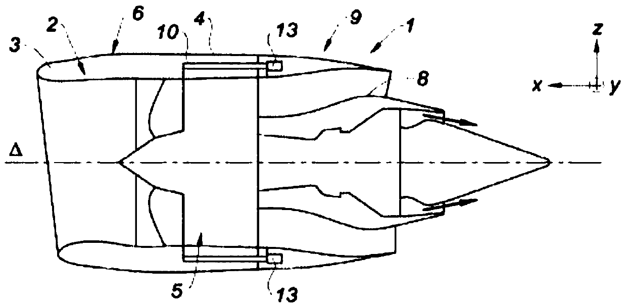
[0044] With reference to the figures, the nacelle 1 has, in a manner known per se, a substantially tubular shape along a longitudinal axis Δ. The nacelle 1 comprises an upstream section 2 with an air intake lip 3 , an intermediate section 4 surrounding a fan 5 of an engine, such as a bypass turbojet, and a downstream section.

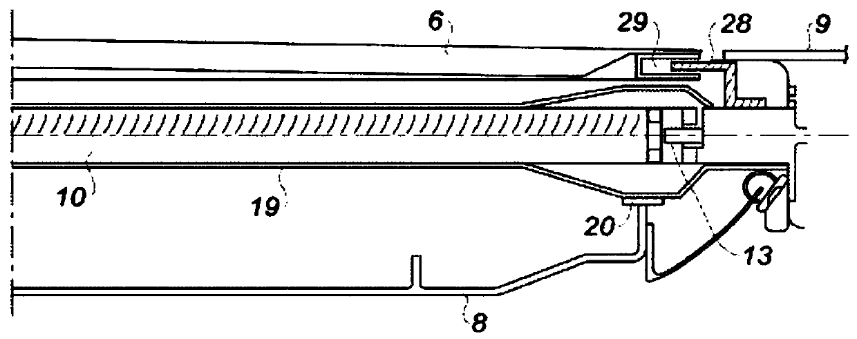
[0045] In particular, the middle section comprises a fan housing 8 surrounding the fan 5 and supporting a fan cowl 6 adapted to be swept externally by the air flow outside the nacelle 1 during flight.

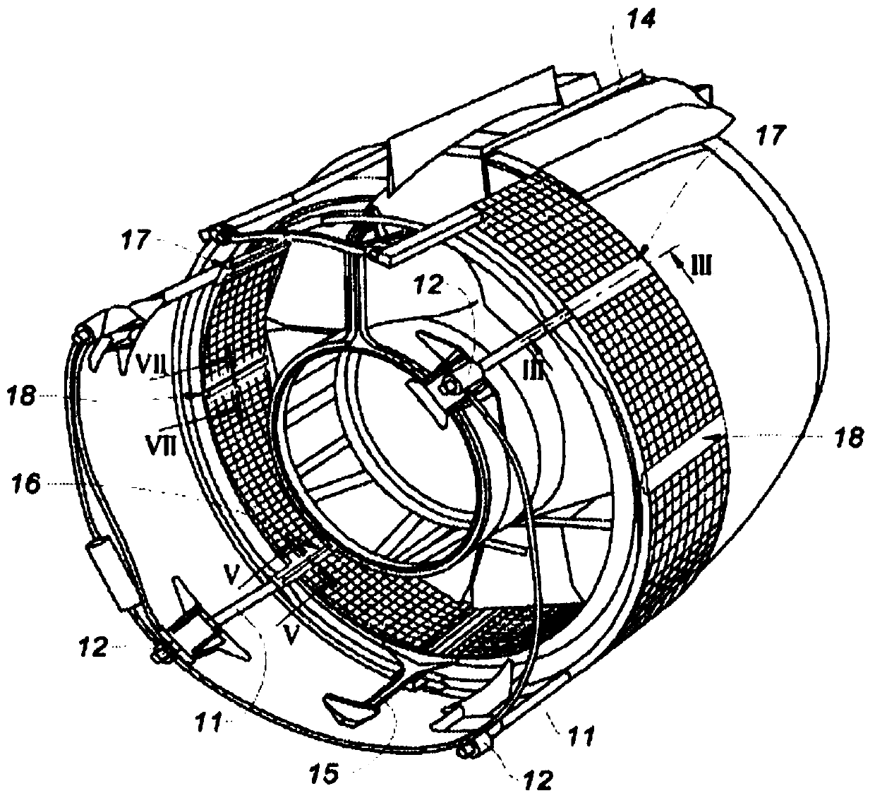
[0046] The downstream section comprises at least one movable cowl 9 comprising thrust reversal means. The movable cowl 9 is connected to the cascade 10 of the thrust reverser and is driven during thrust reversal by actuators, here four electromechanical cylinders, regularly distributed around the axis Δ and comprising fixed Rod 11 to end 13 of the downstream section, and motor 12 fastened to the middle section. During the displacement of the downstream...


PUM


Abstract

The invention concerns a nacelle of an aircraft turbofan engine comprising an air inlet (2) upstream from the engine, a median section (4) intended to surround a fan (5) of the engine and delimited onthe outside by a fan cowl (6) supported by a fan housing to which it is attached at the upstream portion, a downstream section delimiting an annular flow path in which the air is intended to flow andhousing thrust reversal means, the thrust reversal means comprising a movable cowl (9) associated with at least one actuator for moving the movable cowl between a direct jet position, in which it ensures the aerodynamic continuity of the nacelle and an indirect jet position in which it opens up a passage in the nacelle by uncovering gratings arranged around this flow path that receive the cold air flow to return it towards the outside and forwards, the gratings being attached to the movable cowl and sliding with same, the nacelle being characterised in that it comprises a series of guiding devices (16,17,18) distributed around a longitudinal axis (delta) of the nacelle, and each comprising a first guide element (20, 23, 27) secured to the median section and a second guide element (19, 22,24) secured to the downstream section.

Description

technical field [0001] The invention relates to an aircraft nacelle comprising a sliding cascade thrust reverser. Background technique [0002] Aircraft are propelled by one or more propulsion units comprising turbojet engines housed in tubular nacelles. Each propulsion unit is attached to the aircraft by struts usually located under the wings or at the fuselage. [0003] The nacelle usually has a structure comprising an air intake upstream of the engine, an intermediate section for surrounding the fan of the turbojet engine, a downstream section for housing the thrust reverser and for surrounding the combustion chamber of the turbojet engine, and the nacelle usually terminates in As for the nozzle, the outlet of which is located downstream of the turbojet engine. [0004] The thrust reverser is a device that allows to direct the airflow generated by the turbojet engine forward, which allows shortening the landing distance and also limits the stress on the brakes at the la...

Claims


Application Information

Patent Timeline
IPC IPC(8): B64D29/00F02K1/72
CPCB64D29/00F02K1/72F05D2250/75F02K1/09F02K1/70
Inventor 卢瓦·格拉尔麦乐迪·塞丽塞特亚力克西斯·艾欧本杰明·布雷比恩奥利维尔·凯尔布莱尓
Owner SAFRAN NASEL
Learn More