
Method and system applied to loading modeling of crus prosthetic socket

A socket and calf technology, applied in prosthetics, medical science, etc., can solve the problems that the mechanical characteristics of the residual limbs are insufficient, cannot fully reflect the biomechanical performance bearing capacity of the residual limbs, and cannot provide comfortable support for patients, so as to improve Production efficiency, comfort and applicability, and the effect of improving comfort

Pending Publication Date: 2020-08-07
国家康复辅具研究中心
View PDF10 Cites 2 Cited by
  • Summary
  • Abstract
  • Description
  • Claims
  • Application Information

AI Technical Summary

Problems solved by technology

The first one is socket design based on 3D scanning technology, as described in the invention patent with application number 201710619765.7, only considering the geometric shape of the residual limb, and still relying on the experience of technicians to carry out the 3D reconstruction of the socket support interface, cannot fully Reflecting the biomechanical properties of the residual limb and the carrying capacity of each area, the fabricated socket cannot provide comfortable support for the patient
The second type, the design of prosthetic socket based on numerical simulation, although it tries to take the biomechanical characteristics of the residual limb into consideration, is still unable to cope with the complex mechanical characteristics of the residual limb
[0006] It can be seen that, in addition to the constraints such as equipment and material costs, the digital design of the prosthetic socket that meets the needs of biomechanical individualized clinical adaptation has become the core key basic issue that restricts the application of CAM and 3D printing technology in the design and production of sockets, resulting in CAM Neither AM nor AM have been widely used clinically

Method used


Image

  • Method and system applied to loading modeling of crus prosthetic socket
  • Method and system applied to loading modeling of crus prosthetic socket

Examples


Embodiment Construction

[0029] The specific implementation manners of the present invention will be further described in detail below in conjunction with the accompanying drawings and embodiments. The following examples are only used to illustrate the present invention, but not to limit the scope of the present invention.

[0030] The orientation or position relationship terms such as up, down, left, right, inside, outside, front end, rear end, head, and tail in this application document are established based on the orientation or position relationship shown in the drawings. If the drawings are different, the corresponding positional relationship may also change accordingly, so this should not be understood as limiting the scope of protection.

[0031] In the present invention, the terms "installation", "connection", "connection", "connection", "fixation" and so on should be understood in a broad sense, for example, it can be a fixed connection, a detachable connection, or an integrated Connection c...


PUM


Abstract

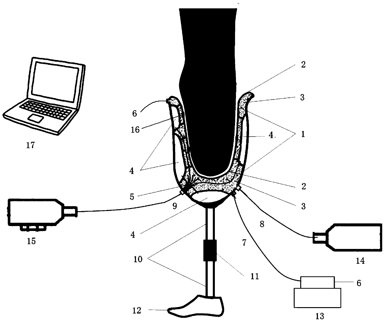
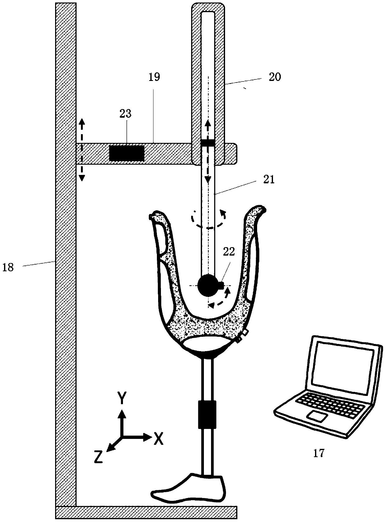
The invention relates to a method and system applied to loading modeling of a crus prosthetic socket. A negative pressure modeling system is used for acquiring the geometrical shape of a socket of a stump in a loading state and correcting the geometrical shape of a socket supporting interface; the corrected geometrical shape of the socket supporting interface is obtained by using a socket three-dimensional scanning system; a supporting interface geometric model of the socket is generated automatically by combining the geometrical shape of the socket supporting interface with a crus socket database and a final digital model of the crus socket is generated in a manner of translating to construct an entity with a specific thickness. Quantitative control over the geometrical morphology of thesupporting interface can be conducted according to the biomechanical property of the stump and the bearing capacity of each area, geometrical modeling of the crus socket of the loading position is achieved, finally digital reconstruction of the socket is achieved through a three-dimensional scanning method, and the three-dimensional scanning method is applied to digital design of the crus socket.

Description

technical field [0001] The invention relates to the field of weight-bearing modeling of residual limbs applied to calf amputee patients and the field of three-dimensional scanning geometric reconstruction thereof, in particular to a method and system for weight-bearing modeling of calf prosthesis sockets. Background technique [0002] The prosthetic socket is an important contact interface connecting the prosthesis and the stump. Its function is not only to accommodate the residual limb comfortably, but also plays an important role in effectively transmitting the supporting force to the distal end of the prosthesis. The rationality of its design is directly Affects the comfort and convenience of prosthetic use. Due to the significant individual characteristics of the residual limbs of amputee patients, it is necessary to customize the prosthetic socket differently from person to person. [0003] Traditional socket customization has gone through operations such as plaster ba...

Claims


Application Information

Patent Timeline
IPC IPC(8): A61F2/80A61F2/76
CPCA61F2/80A61F2/76A61F2002/7615A61F2002/7685A61F2002/7635A61F2240/002
Inventor 莫中军杨洁萌张明峥王振泽赵立伟樊瑜波
Owner 国家康复辅具研究中心
Learn More