Pre-pressing limiting seismic mitigation and absorption method and device for bridge
A vibration reduction and isolation and preloading technology, which is applied in the field of bridge vibration reduction, can solve problems such as limited service life, bridge pier damage, and poor economy, and achieve the effects of low manufacturing, use and maintenance costs, reduced earthquake response, and reliable and durable structures
- Summary
- Abstract
- Description
- Claims
- Application Information
AI Technical Summary
Problems solved by technology
Method used
Image
Examples
Embodiment 1
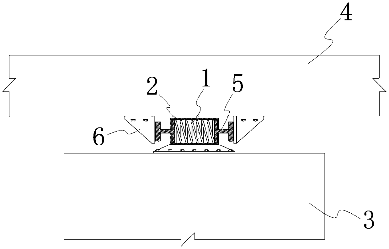
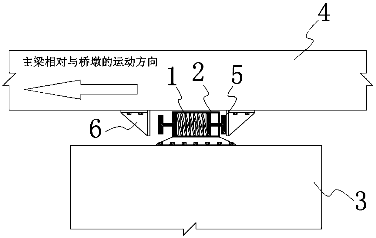
[0030] see Figure 1 ~ Figure 2 , is a preload limit shock absorbing device for a bridge, including a preload limit unit, the preload limit unit includes a preload spring 1 and a preload box 2 for compressing the preload spring, and the preload limit unit It is arranged between the bridge pier 3 and the main girder 4 , and the compression direction of the preload spring 1 is perpendicular to the extension direction of the bridge pier 3 . In this embodiment, the preload spring 1 is a metal coil spring.
[0031] The pre-compression box 2 is fixedly arranged on the pier 3, and the side of the pier 3 close to the main girder 4 is the top surface. For a continuous girder bridge, there is only one main girder 4. When the space is installed, the preloaded spacer unit can be installed between the top surface of the bridge pier 3 and the main girder 4 .
[0032] The pre-compression box 2 is fixedly arranged on the top surface of the bridge pier 3 . The pre-compression spring 1 is co...
Embodiment 2
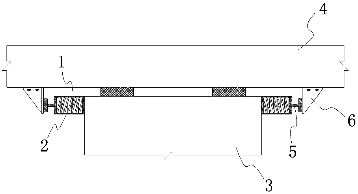
[0036] see Figure 3 ~ Figure 4 , the surface around the top surface of the pier 3 is the side. When the installation space between the top surface of the pier 3 and the main girder 4 is small, the pre-compression limit unit can be installed between the side of the pier 3 and the main girder 4. In this embodiment, there are two pre-compression limiting units, and the two pre-compression boxes 2 are respectively arranged on the two corresponding sides of the bridge pier 3 . The two preload springs 1 respectively act on the two limit blocks 6 on the main beam 4 through the two connecting rods 5 .
Embodiment 3
[0038] see Figure 5 ~ Figure 7, for a simply supported bridge, there are two main girders 4 . There are two preloading limit units, and the end of the connecting rod 5 close to the preloading spring 1 is provided with a forward limit 7 and a reset limit 8, and the forward limit 7 and the reset limit 8 are arranged along the extension direction of the connecting rod 5 , The preload spring 1 is arranged between the forward limit 7 and the return limit 8, and the connecting rod 5 performs reciprocating compression on the preload spring 1 through the forward limit 7 and the return limit 8. The pre-compression box 2 is provided with a through hole for the connecting rod 5 to pass through. The other end of the connecting rod 5 is connected to the main beam 4 , and the two preloaded position-limiting units are respectively connected to the two main beams 4 through the connecting rod 5 .
[0039] During the earthquake, when the main girder 4 moves toward the bridge pier 3, the prel...
PUM
 Abstract
Description
Claims
Application Information
 - R&D
- Intellectual Property
- Life Sciences
- Materials
- Tech Scout
- Unparalleled Data Quality
- Higher Quality Content
- 60% Fewer Hallucinations
Browse by: Latest US Patents, China's latest patents, Technical Efficacy Thesaurus, Application Domain, Technology Topic, Popular Technical Reports.
© 2025 PatSnap. All rights reserved.Legal|Privacy policy|Modern Slavery Act Transparency Statement|Sitemap|About US| Contact US: help@patsnap.com


