
Seismic substation support post equipment connecting device capable of adjusting installation position

A technology for installation location and equipment connection, applied in the direction of anti-seismic equipment, etc., can solve the problems of lead alloy damping and shock absorbing device 3 having no restoring force, lead material yield strength is small, and has no shock-absorbing effect, etc., so as to meet the requirements of normal operation and protect Electrical equipment, the effect of reducing the seismic response

Inactive Publication Date: 2016-03-16
TONGJI UNIV
View PDF9 Cites 5 Cited by
  • Summary
  • Abstract
  • Description
  • Claims
  • Application Information

AI Technical Summary

Problems solved by technology

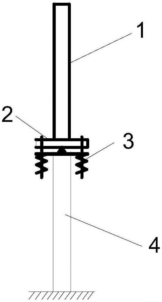
[0007] (1) There is no shock absorption effect in the vertical direction, and it may be damaged due to the impact of the main body of the electrical equipment 1 on the fulcrum under the action of a vertical earthquake;
[0008] (2) Since the yield strength of the lead material is very small, the long-term wind load will loosen the connection;
[0009] (3) The lead alloy damping and shock absorbing device 3 has no restoring force, and it can only perform one-way yield deformation under the action of an earthquake, so the connection tends to loosen under the action of an earthquake, and there are certain defects in use

Method used


Image

  • Seismic substation support post equipment connecting device capable of adjusting installation position
  • Seismic substation support post equipment connecting device capable of adjusting installation position
  • Seismic substation support post equipment connecting device capable of adjusting installation position

Examples


Embodiment 1

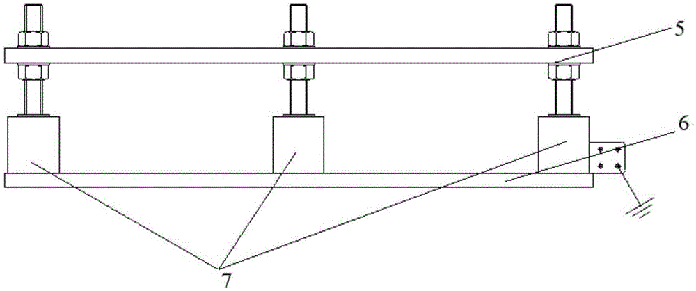
[0041] Such as figure 2As shown, an anti-seismic substation pillar equipment connection device with adjustable installation position is used to connect electrical equipment 1 and pillar 4, including upper metal plate 5, lower metal plate 6 and six damping bolts 7, upper metal plate 5 and The material of the lower metal plate 6 is generally the steel plate material commonly used in substation construction, and the thickness of the steel plate should meet the normal use requirements of the equipment under the action of anti-seismic vibrations and the structural requirements stipulated in relevant specifications.

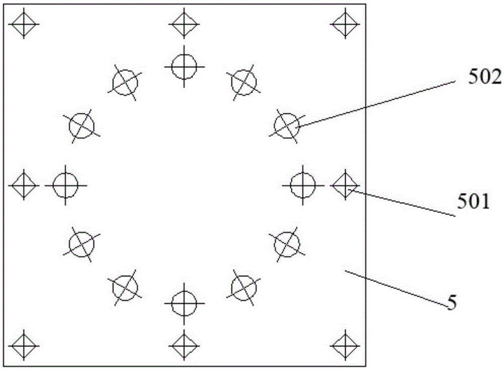
[0042] According to the national standard "GB50017-2003" and the corresponding regulations, the damping bolt installation holes a501 are arranged on the upper metal plate 5, and the parameters such as the number, position and hole diameter are set according to the structural characteristics of the electrical equipment 1, the strength of the material, the anti-seismic r...

Embodiment 2

[0061] In this embodiment, eight damping bolts 7 are provided, and the rest are the same as in Embodiment 1.

Embodiment 3

[0063] In this embodiment, four damping bolts 7 are provided, and the rest are the same as in Embodiment 1.


PUM


Abstract

The invention relates to a seismic substation support post equipment connecting device capable of adjusting an installation position. The seismic substation support post equipment connecting device is used for connecting electric equipment (1) and a support post (4), and comprises an upper metal plate (5), a lower metal plate (6) and at least four damping bolts (7), wherein the bottom ends of the damping bolts (7) are fixed to the lower metal plate (6); and the upper metal plate (5) passes through damping bolt mounting holes a (501) formed in the upper metal plate, and movably sleeves the damping bolts (7). When the seismic substation support post equipment connecting device is used, firstly, the lower metal plate (6) is connected to the top end of the support post (4); secondly, the upper metal plate (5) is connected with an electrical equipment (1) body; and finally the installation position of the electrical equipment (1) body is adjusted by adjusting the lengths of the damping bolts (7) between the upper metal plate (5) and the lower metal plate (6). Compared with the prior art, the installation accuracy of the equipment can be improved; seismic response of the equipment is reduced; and the expensive electrical equipment is protected.

Description

technical field [0001] The invention belongs to the field of anti-seismic technology of substation equipment, and in particular relates to an anti-seismic substation pillar equipment connection device with adjustable installation position. Background technique [0002] The substation is a key part of the power lifeline project. In a high-voltage substation, the structure of most equipment is porcelain or composite insulators or bushings on the upper part, and steel structural pillars or supporting frames on the lower part, such as circuit breakers and lightning arresters. , capacitors, isolating switches, etc. High-voltage electrical equipment has a large mass and a high center of gravity, and is prone to damage under the action of a strong earthquake, which will lead to the paralysis or even complete collapse of the power system. The failure of the power system will cause serious disasters and huge economic losses, not only affecting the post-earthquake disaster relief wor...

Claims


Application Information

Patent Timeline
Patent Type & Authority Applications(China)
IPC IPC(8): H02B1/54
CPCH02B1/54
Inventor 谢强何畅
Owner TONGJI UNIV
Learn More