Anti-floating anchor rod structure penetrating through water-rich gravel bottom layer and construction method thereof

An anti-floating anchor and gravel layer technology is applied in the fields of infrastructure engineering, sheet pile walls, protection devices, etc. Problems such as poor pile holding force, to achieve the effect of safe, stable and reliable structure, simple and smooth construction process, and low cost

Inactive Publication Date: 2020-08-07
CHINA FIRST METALLURGICAL GROUP
View PDF3 Cites 1 Cited by
  • Summary
  • Abstract
  • Description
  • Claims
  • Application Information

AI Technical Summary

Problems solved by technology

[0006] The present invention aims at the deficiencies of the prior art, and provides an anti-floating anchor structure and its construction method for piercing the bottom layer of water-rich gravel to solve the problem of difficulty in pile construction of the anti-floating anchor that contains the water-rich gravel layer under the soil layer, which is reasonable Adding grouting flower tubes in the middle of the anti-floating anchor reinforcement passing through the water-rich gravel layer and adding a protective section with a guide head at the end of the reinforcement, and proposing targeted structural settings and construction techniques, can effectively solve the problem of piercing through the water-rich gravel layer. Problems such as inability to form holes, insufficient pull-out resistance of piles, poor pile bearing strength of pile heads and exposed tendons, etc.

Method used


Image

  • Anti-floating anchor rod structure penetrating through water-rich gravel bottom layer and construction method thereof
  • Anti-floating anchor rod structure penetrating through water-rich gravel bottom layer and construction method thereof
  • Anti-floating anchor rod structure penetrating through water-rich gravel bottom layer and construction method thereof

Examples


Embodiment 1

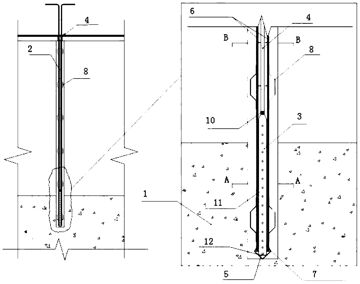
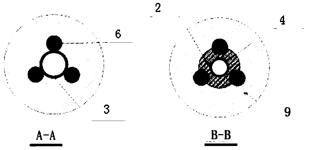
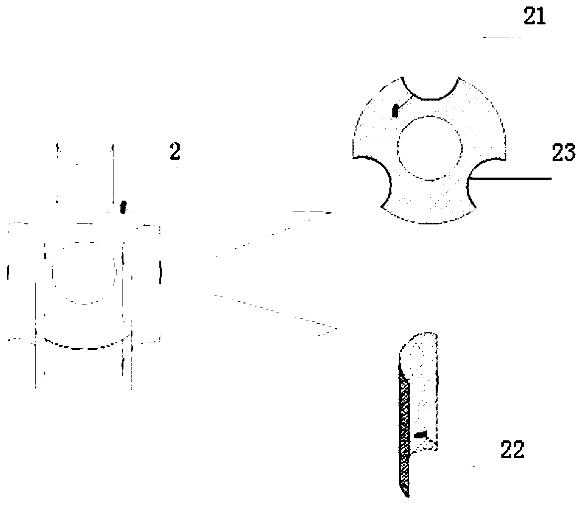
[0034] An anti-floating anchor structure for penetrating a water-rich gravel bottom layer, comprising a plurality of steel tendons 6 (ie, anti-floating anchors), fixing pieces 2, grouting flower tubes 3, grouting hoses 4, guide heads 5 and the like. Its anti-floating anchor rod is a steel tendon 6 composed of more than 3 steel bars. The steel tendons 6 are longitudinally arranged in parallel and are fixed by the fixing piece 2. The bottom ends of the steel tendons 6 extend to the bottom layer of water-rich gravel. Vertically arranged, the bottom end of the grouting flower tube 3 is provided with a guide head 5 . The fixed piece 2 is composed of an inner support piece 21 and a number of longitudinal galvanized binding pieces 22, the inner support piece 21 is arranged horizontally, the galvanized tie piece 22 is arranged vertically, and the outer circumference of the inner support piece 21 is evenly provided with a number of inner support card slots 23. The galvanized binding p...


PUM


Abstract

The invention provides an anti-floating anchor rod structure penetrating through a water-rich gravel bottom layer and a construction method thereof. The anti-floating anchor rod structure comprises agrouting hose, a grouting floral tube, fixing pieces and a plurality of steel bar bundles evenly distributed in parallel in the longitudinal direction, wherein the steel bar bundles are fixed throughthe fixing pieces, the bottom ends of the steel bar bundles extend to penetrate through the water-rich gravel bottom layer, the bottom end of the grouting hose and the top end of the grouting floral tube are in butt joint, fixedly connected and longitudinally arranged, the grouting floral tube is located on the water-rich gravel bottom layer, the top end of the grouting floral tube exceeds the water-rich gravel bottom layer by at least 20 cm, a guide head is arranged at the end of the bottom end of the grouting floral tube, and the grouting floral tube is positioned among the plurality of steel bar bundles and is fixedly connected with the steel bar bundles. According to the structure and the method, the steel bar bundles directly penetrate through the water-rich gravel layer to form a pile, anti-floating and mechanical normal hole forming construction is effectively enhanced, a pile casing is avoided, and meanwhile, the quality problems that during water-rich gravel layer penetrating,hole forming cannot be achieved, the pile forming pulling resistance is insufficient, the pile head forming bearing capacity is poor, and steel bars are exposed are solved, and the structure has theadvantages of being convenient and standard to construct and easy to manufacture and practical.

Description

technical field [0001] The invention belongs to the field of anti-floating anchor grouting auxiliary devices for building foundations, in particular to an anti-floating anchor structure and a construction method for penetrating a water-rich gravel bottom. Background technique [0002] Due to the high groundwater level, anti-floating considerations are often required for building foundation projects near rivers and rivers. However, in actual construction, it has been found that with the development of history, there are often gravel riverbeds in the deep underground, and geological survey points are prone to failure. After surveying the location and drilling into the water-rich gravel layer, it is often necessary to face the following construction difficulties: [0003] (1) It is difficult to form holes in the water-rich gravel layer, and it is necessary to change the length, planting reinforcement, and reinforcement design of the anti-floating anchor pile, or increase the me...

Claims


Application Information

Patent Timeline
Patent Type & Authority Applications(China)
IPC IPC(8): E02D31/12E02D5/74E02D15/04
CPCE02D5/74E02D15/04E02D31/12
Inventor 夏志聪赵海莲马越胡静文胡宏坤
Owner CHINA FIRST METALLURGICAL GROUP
Why Eureka
Try Eureka