A gauze structure with unique edge design

A kind of gauze, unique technology, applied in the direction of building components, building structure, construction, etc., can solve the problems of reducing anti-mosquito, affecting aesthetics, crease, etc., to beautify the visual effect, increase the blocking of mosquitoes and flies, and protect the integrity Effect

Active Publication Date: 2021-07-13
LIXIN FUYA GAUZE CO LTD
View PDF4 Cites 0 Cited by
  • Summary
  • Abstract
  • Description
  • Claims
  • Application Information

AI Technical Summary

Problems solved by technology

[0003] The edge structure of the gauze in the prior art is relatively common, and the gauze overall is not beautiful after installation; the joint of the two gauzes is only automatically closed by the magnets sewn on the edge of the gauze, which is easy to be too violent during the opening and closing process As a result, the magnets are displaced or damaged, which reduces the fit between the two pieces of gauze; at the same time, the gauze usually needs to be disassembled in the season when it is not in use. If it is still installed, the user usually uses a clip The gauze is fixed on both sides of the door frame. This fixing method may cause damage to the gauze itself or produce irregular creases, which will affect the aesthetics and reduce the anti-mosquito effect in the subsequent use process; therefore, the present invention proposes A gauze structure with unique edge design to solve the above problems

Method used


Image

  • A gauze structure with unique edge design
  • A gauze structure with unique edge design
  • A gauze structure with unique edge design

Examples


Embodiment 1

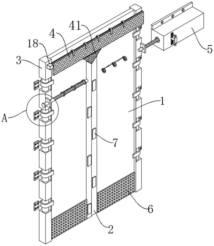
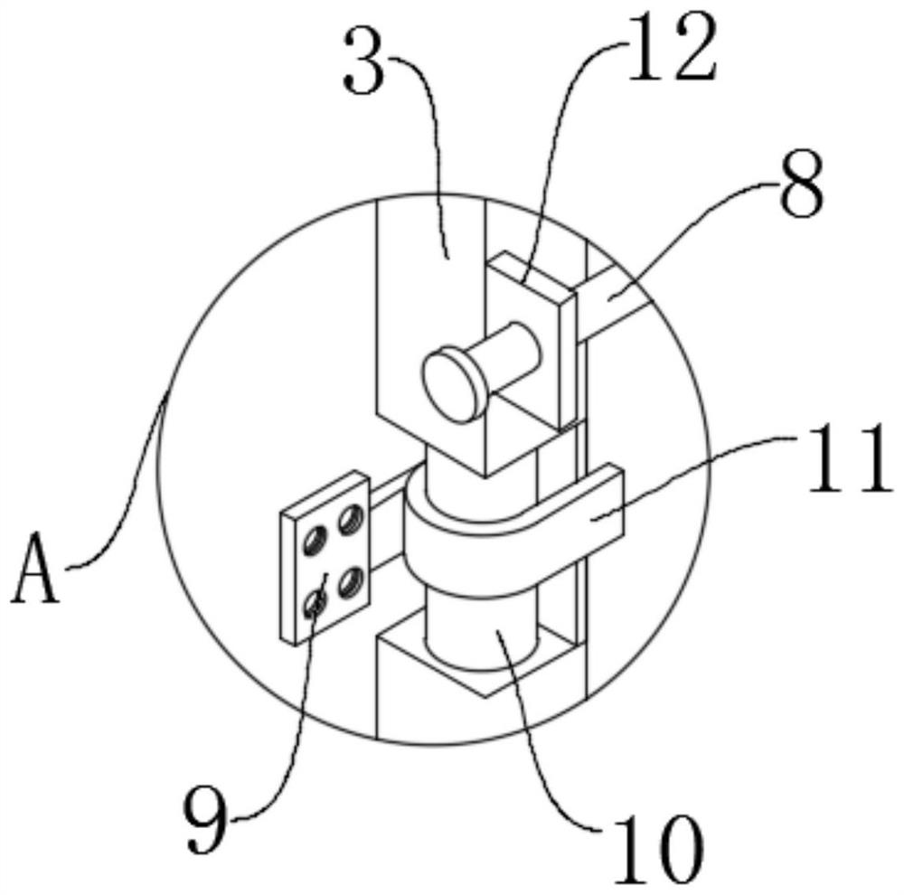
[0042] see Figure 1-2 And 5-6, a gauze structure with a unique edge design, including two gauze bodies 1 and an expansion box 5, a mounting plate 13 is fixedly connected to the upper end of the expansion box 5, and the mounting plate 13 is connected to the wall by fastening bolts. Active connection; a cylindrical edge 10 is fixedly connected to the side of the gauze body 1, and a shrinking edge block 3 is fixedly connected between the adjacent cylindrical edges 10; the outer side of the cylindrical edge 10 is matched with a hardware clip A11, and one side of the hardware clip A11 A fixed piece A9 is fixedly connected, and the fixed piece A9 is movably connected with the wall through fastening bolts; the upper end of the gauze body 1 is provided with a light-shielding structure 4, and the light-shielding structure 4 includes a connecting frame, and the connecting frame is arranged between the upper edges of the two gauze bodies 1. Between the two ends of the front side of the ...

Embodiment 2

[0046] see Figure 2-3 , based on Embodiment 1, there is another difference in that;

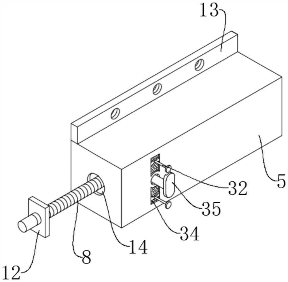
[0047] A fixing piece B12 is fixedly connected to one side of the upper end crimping block 3, and the fixing piece B12 is movably connected with an adjusting screw 8 through a thread, and the adjusting screw 8 is movably arranged inside the expansion box 5;

[0048] The adjusting screw 8 is movably connected with a number of adjusting coils 15 through threads. The adjusting coils 15 are fixedly connected to the gauze body 1 through the fixing block A17. The waterproof cloth is sewn on the surface of the gauze body 1;

[0049] An adjusting motor 23 is fixedly connected to the inner wall of the expansion box 5, and a connecting rod 24 is fixedly connected to the output shaft of the adjusting motor 23. In the adjustment screw 8, the adjustment screw 8 penetrates the installation hole 14 on one side of the expansion box 5 and is movably connected with the installation hole 14;

[0050] In the...

Embodiment 3

[0052] see Figure 7-8 , based on Embodiments 1 and 2, there is a difference in that;

[0053] One end of the adjusting screw 8 close to the mounting hole 14 is matched with a clamping structure, and the clamping structure is arranged inside the expansion box 5; Threaded connection, the center of the threaded half ring 26 is fixedly connected with a clamping rod 27, and the end of the clamping rod 27 is fixedly connected with an oblique rod;

[0054] A slide rail 28 is provided in the center of the inclined rod, the end of the clamp rod 27 is slidably connected to the limit groove of the limit rod 25 through the slide rod, and the end of the limit rod 25 is fixedly connected to the inner wall of the expansion box 5; the slide rails 28 of the two inclined rods A central rod 29 is connected through the junction, and the central rod 29 is slidably connected inside the slide rail 28;

[0055] The center rod 29 is fixedly connected to the end of the adjustment rod 31, the adjustm...


PUM


Abstract

The invention discloses a gauze structure with a unique side shape design, which belongs to the technical field of gauze installation. A gauze structure with a unique edge design, including two gauze bodies and an expansion box, the upper end of the expansion box is fixedly connected with a mounting plate, and the mounting plate is movably connected to the wall through fastening bolts; the gauze The side of the net body is fixedly connected with a cylindrical edge, and a shrinkage edge block is fixedly connected between the adjacent cylindrical edges; the outer side of the cylindrical edge is matched with a hardware clip A, and one side of the hardware clip A is fixedly connected with a The fixed piece A is movably connected to the wall through fastening bolts; a connection frame is fixedly connected between the upper edge of the two gauze bodies, and a fixed block B is fixedly connected to both ends of the front side of the connection frame, A clamping rod is fixedly connected between the two fixed blocks B; the present invention solves the problem that the edge shape of the gauze in the prior art is not beautiful enough and is easy to be damaged during the opening and closing process and the fixed opening process.

Description

technical field [0001] The invention relates to the technical field of gauze installation, in particular to a gauze structure with a unique edge design. Background technique [0002] The gauze is a relatively common anti-mosquito tool in the prior art. It can be ventilated and can prevent mosquitoes from entering the room at will in the summer, and it is easy to open and close the process. It closes automatically, so it is the preferred way of preventing mosquitoes for most people. [0003] The gauze edge structure in the prior art is relatively common, and the gauze as a whole is not aesthetically pleasing after installation; the connection between the two gauze meshes is only automatically closed by mutual attraction by the magnets sewn on the edge of the gauze, which is easy to be too violent during the switching process. However, the magnet is displaced or damaged, which reduces the fit between the two pieces of gauze. At the same time, the gauze usually needs to be dis...

Claims


Application Information

Patent Timeline
Patent Type & Authority Patents(China)
IPC IPC(8): E06B9/52
CPCE06B9/52E06B2009/527
Inventor 朱亚军朱新亚王菊芬王硕朱映旭殷艺瑶王恺
Owner LIXIN FUYA GAUZE CO LTD
Why Eureka
Try Eureka