Check patentability & draft patents in minutes with Patsnap Eureka AI!

Multi-speed change gear box

A technology of transmission gearbox and planetary gear set, applied in the direction of vehicle transmission, gear transmission, belt/chain/gear, etc., can solve the problems of increased maintenance cost, poor transmission stability, broken transmission system, etc., to achieve good transmission Ratio adjustment range, large transmission ratio application range, good transmission stability

Inactive Publication Date: 2020-08-07
维艾迪(北京)新能源汽车科技有限公司
View PDF8 Cites 2 Cited by
  • Summary
  • Abstract
  • Description
  • Claims
  • Application Information

AI Technical Summary

Problems solved by technology

[0002] Most of the existing gearboxes use direct gear transmission between large and small gears to achieve the purpose of acceleration or deceleration. However, for high transmission ratio transmissions, this structure either requires too much motor or poor transmission stability. At the same time, the strength requirements for the input shaft and output are also high, and a thicker shaft is needed to achieve acceleration or deceleration with a high transmission ratio, which affects the cost and volume of the entire gearbox. The size and production cost have a great impact; most bicycles with shifting function use traditional chain transmission, but this structure is not smooth in the process of shifting gears, and it may break if it falls down while riding Transmission system
Thus affecting the service life of the bicycle, or increasing maintenance costs

Method used


Image

  • Multi-speed change gear box
  • Multi-speed change gear box
  • Multi-speed change gear box

Examples


Embodiment Construction

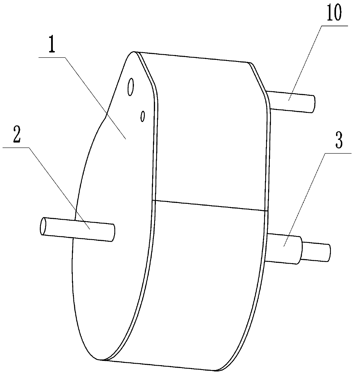
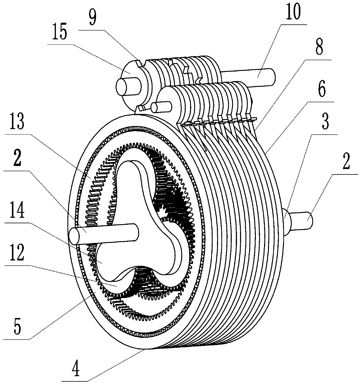
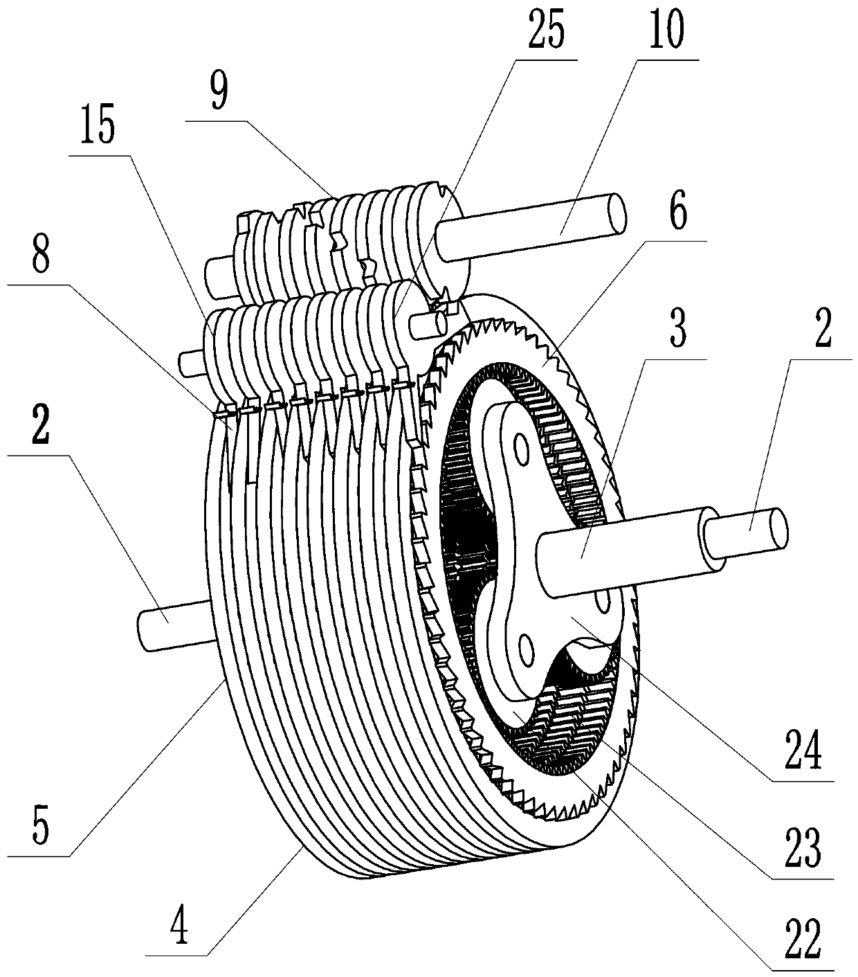
[0014] Such as figure 1 , figure 2 , image 3 , Figure 4 , Figure 5 As shown, a multi-stage transmission gearbox provided by the present invention includes a box body 1, an input shaft 2, an output shaft 3, and a variable speed unit 4. One end of the input shaft 2 is connected to a motor, and the other end is connected to a variable speed unit 4. The other end of 4 is connected to the output shaft 3. The input shaft 2 and the output shaft 3 are both fixed on the housing 1 through bearings. The transmission unit 4 includes a driving planetary gear set 5 and a driven planetary gear set 6, the driving planet The gear set 5 includes two driving sun gears 11, two driving planetary gear sets 12, and two driving outer ring gears 13, and a driving planet carrier 14. The two driving sun gears 11 and the two driving planetary gear sets 12 Correspondingly cooperate with the two active outer ring gears 13 and are arranged in sequence along the axial direction of the input shaft 2. The p...


PUM


Abstract

The invention discloses a multi-speed change gear box. The multi-speed change gear box comprises a box body, an input shaft, an output shaft and a speed change unit, wherein one end of the input shaftis connected with a motor, the other end of the input shaft is connected with the speed change unit, the other end of the speed change unit is connected with the output shaft, the input shaft and theoutput shaft are fixed to the box body through bearings, and the speed change unit comprises a driving planetary gear set and a driven planetary gear set; the driving planetary gear set comprises a plurality of driving sun gears, a plurality of driving planetary wheel sets, a plurality of driving outer gear rings and one driving planetary carrier, wherein the driving sun gears, the driving planetary wheel sets and the driving outer gear rings are consistent in number; and the driven planetary gear set comprises a plurality of driven sun gears, a plurality of driven planetary wheel sets, a plurality of driven outer gear rings and one driven planet carrier, wherein the plurality of driven sun gears, the plurality of driven planetary wheel sets and the plurality of driven outer gear rings are consistent in number and are matched in a corresponding mode, and the driven planet carrier is fixedly connected with the driving planet carrier.

Description

Technical field [0001] The invention relates to a multi-stage gearbox. Background technique [0002] Most of the existing gearboxes use gear transmission between large and small gears to achieve the purpose of acceleration or deceleration. However, this structure requires too much motor for high transmission ratio speed change, or the transmission stability is poor. At the same time, the strength requirements for the input shaft and output are also high. A thicker shaft is required to achieve high transmission ratio acceleration or deceleration, which affects the cost and volume of the entire gearbox. Some transmission methods through multi-stage gears also affect the box body. The size and production cost have a greater impact; and most bicycles with shifting function use traditional chain transmission, but this structure is not smooth in the process of shifting. If you fall while riding, you may break Variable speed system. This affects the life of the bicycle or increases ma...

Claims


Application Information

Patent Timeline
IPC IPC(8): F16H3/70F16H55/17F16H57/08F16H59/02
CPCF16H3/70F16H55/17F16H57/08F16H59/02F16H2055/176F16H2057/085F16H2200/2007
Inventor 蔡明
Owner 维艾迪(北京)新能源汽车科技有限公司
Features
  • R&D
  • Intellectual Property
  • Life Sciences
  • Materials
  • Tech Scout
  • Unparalleled Data Quality
  • Higher Quality Content
  • 60% Fewer Hallucinations
Learn More