Battery comprehensive detection device

A comprehensive detection and equipment technology, applied in the direction of measuring devices, conveyor objects, instruments, etc., can solve the problems of single detection function, long time, missed detection, multiple detection, etc., to achieve accurate detection process, reduce missed detection, and save time. The effect of cost and labor

Active Publication Date: 2020-08-07
东莞市爱康智能技术有限公司
View PDF14 Cites 4 Cited by
  • Summary
  • Abstract
  • Description
  • Claims
  • Application Information

AI Technical Summary

Problems solved by technology

[0002] With the development of science and technology, mobile phones have become an indispensable communication device for people. In order to make people use mobile phones safely and securely, manufacturers need to strictly control the performance of mobile phones during the process of manufacturing mobile phones, especially The detection of mobile phone batteries is the most important link for manufacturers. Due to the variety of mobile phone battery testing items, the current mobile phone batteries need to use a variety of equipment in the testing process. However, the testing functions of each testing equipment are relatively different. Single, which leads to the fact that the mobile phone battery must be put into the corresponding equipment for testing in order to complete all the testing items. This not only takes a long time for testing, but also is prone to missed testing and multi-testing caused by human errors between testing items. and other situations, therefore, it is necessary to produce a battery comprehensive testing equipment, which can set as many items as possible on the same equipment that need to be tested by the mobile phone battery, realize the automatic detection of multiple functions, and reduce the detection process in multiple devices. The situation of transfer between them not only saves time and labor in the detection process, but also reduces the probability of missing and over-testing caused by human errors, ensuring the accuracy, efficiency and stability of the detection process

Method used


Image

  • Battery comprehensive detection device
  • Battery comprehensive detection device
  • Battery comprehensive detection device

Examples


Embodiment Construction

[0025] The present invention will be further described below in conjunction with accompanying drawing:

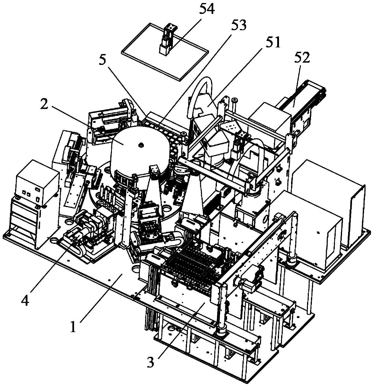
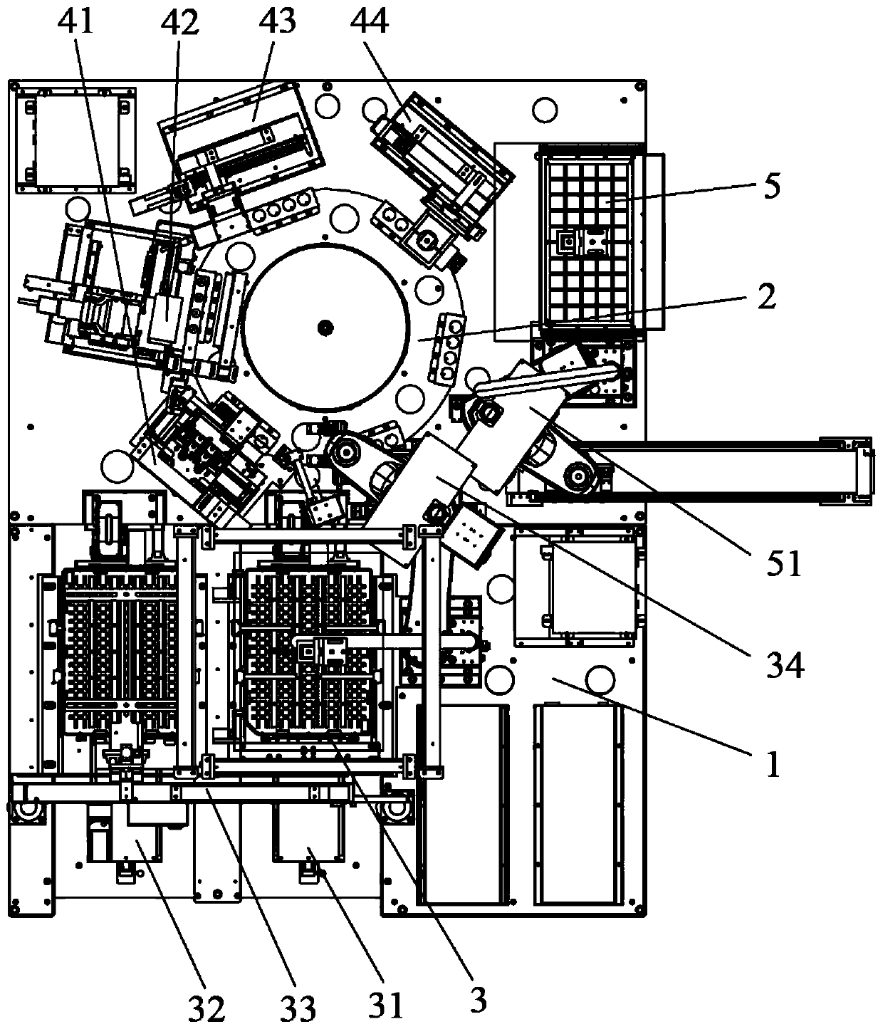
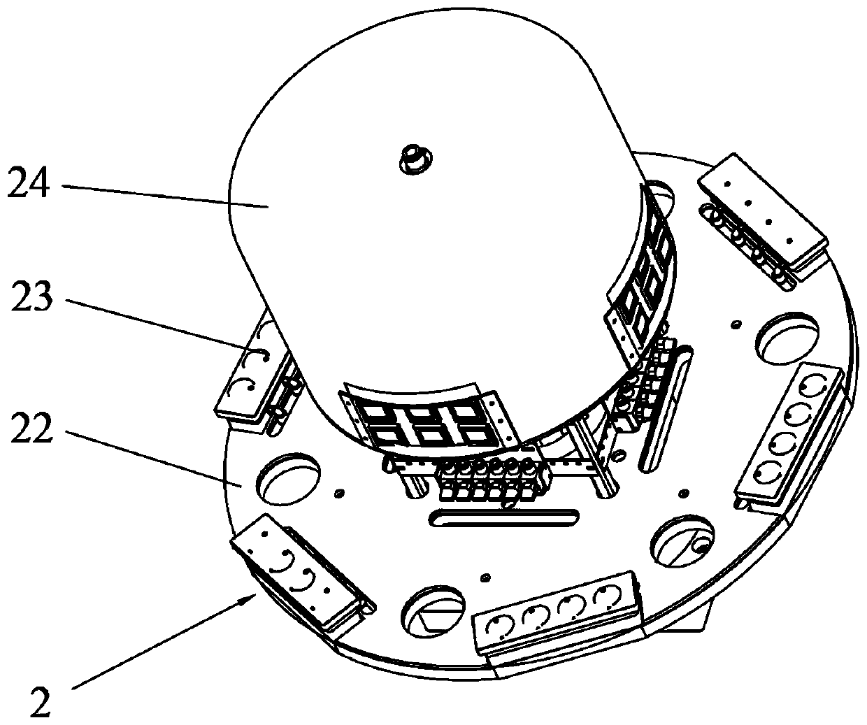
[0026] like Figure 1-11 As shown, a battery comprehensive detection equipment includes a frame 1, a turntable device 2, a feeding device 3, a detection device 4 and a feeding device 5, the turntable device 2 is fixedly installed on the frame 1, the feeding device 3, the detection device The device 4 and the unloading device 5 are sequentially installed on the frame 1 along the rotation direction of the turntable device 2 and correspond to the outer periphery of the turntable device 2. The detection device 4 includes a voltage internal resistance detection mechanism 41 arranged around the outer periphery of the turntable device 2, a temperature With the pole detection mechanism 42, the thickness detection mechanism 43 and the size detection mechanism 44, in this design, the voltage internal resistance detection mechanism 41, the temperature and the pole detection mechanism ...


PUM


Abstract

The invention provides a battery comprehensive detection device. The device comprises a rack, a turntable device, a feeding device, a detection device and a discharging device. The turntable device isfixedly mounted on the rack. The feeding device, the detecting device and the discharging device are sequentially installed on the rack in the rotating direction of the rotary disc device and correspond to the periphery of the rotary disc device. The detection device comprises a voltage internal resistance detection mechanism, a temperature and pole detection mechanism, a thickness detection mechanism and a size detection mechanism which are arranged around the periphery of the turntable device. Automatic detection of multiple functions can be achieved, the situation that the detection process is transferred among multiple devices is reduced, time consumption and labor cost of the detection process are saved, the probability of missing detection and excessive detection caused by human errors is reduced, and accuracy, high efficiency and stability of the detection process are guaranteed.

Description

technical field [0001] The invention relates to the field of automatic testing equipment, in particular to a battery comprehensive testing equipment used for testing mobile phone batteries. Background technique [0002] With the development of science and technology, mobile phones have become an indispensable communication device for people. In order to make people use mobile phones safely and securely, manufacturers need to strictly control the performance of mobile phones during the process of manufacturing mobile phones, especially For the detection of mobile phone batteries, it is the most important link for manufacturers. Due to the various items of mobile phone battery testing, the current mobile phone batteries need to use a variety of equipment in the testing process. However, the testing functions of each testing equipment are relatively different. Single, which leads to the fact that the mobile phone battery must be put into the corresponding equipment for testing ...

Claims


Application Information

Patent Timeline
Patent Type & Authority Applications(China)
IPC IPC(8): G01D21/02B65G29/00B65G47/91
CPCB65G29/00B65G47/912B65G2201/0258G01D21/02
Inventor 蒋芳华袁楚辉
Owner 东莞市爱康智能技术有限公司
Why Eureka
Try Eureka